CAE Software【Femtet】Murata Software Co., Ltd.

Example7 Temperature Change of a Heating Plate by Changing Velocity and Temperature of Incoming Flow
General
-
Heat dissipation of a heating plate by the forced convection is solved by the transient analysis.
The behavior by changing velocity and temperature of the incoming fluid is analyzed.
-
The temperature distribution and the heat flux vectors are solved.
-
Unless specified in the list below, the default conditions are applied.
Analysis Space
|
Item |
Setting |
|
Analysis Space |
2D
Thickness in depth direction: 300mm |
|
Model Unit |
mm |
Analysis Conditions
|
Item |
Setting |
|
Solver |
Fluid Analysis [Bernoulli] Thermal analysis [Watt] |
|
Analysis Type |
Fluid analysis: Transient analysis Thermal analysis: Transient analysis |
|
Laminar Flow/Turbulent Flow |
Select Turbulent Flow |
|
Ambient Temperature |
0[deg] |
|
Meshing Setup |
General Mesh size: 10[mm] |
|
Tab |
Setting Item |
Setting |
||||||||
|
Transient Analysis |
Table |
|
||||||||
|
Initial Temperature |
Use ambient temperature (0[deg]) |
Model
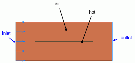
The material of Air (000_Air) is set to a rectangular sheet body. The boundary conditions of inlet and outlet are set on the left edge and the right edge respectively.
A heat source of thin flat plate is defined by the rectangle sheet body.
The slip wall outer boundary condition is applied to the top and bottom edges where the boundary condition is not set.

Body Attributes and Materials
|
Body Number/Type |
Body Attribute Name |
Material Name |
|
0/Solid |
air |
000_Air(*) |
|
1/Solid |
hot |
hot |
* Available from the material DB
The material properties of the thin flat plate are set as follows.
|
Material Name |
Tab |
Properties |
|
hot |
Solid/Fluid |
Solid |
|
Thermal conductivity |
1×10^5 |
|
|
Specific heat |
1×10^3 |
|
|
Density |
1×10^3 |
The heat source of the thin flat plate is set on the heat source tab as follows.
|
Body Attribute Name |
Tab |
Setting |
|
hot |
Heat source |
100W |
Boundary Condition
|
Boundary Condition Name/Topology |
Tab |
Boundary Condition Type |
Setting |
||||||||||||||||||||||||||||||
|
Inlet/Edge |
Fluid-Thermal |
Inlet |
Forced Inflow Select “Time dependency”. Weight Function
Incoming fluid temperature : Direct entry : 25[deg] Select Time dependency. Weight Function
|
||||||||||||||||||||||||||||||
|
Outlet/Face |
Fluid-Thermal |
Outlet |
Natural Outflow |
||||||||||||||||||||||||||||||
|
Outer Boundary Condition |
Fluid-Thermal |
Slip Wall |
– |
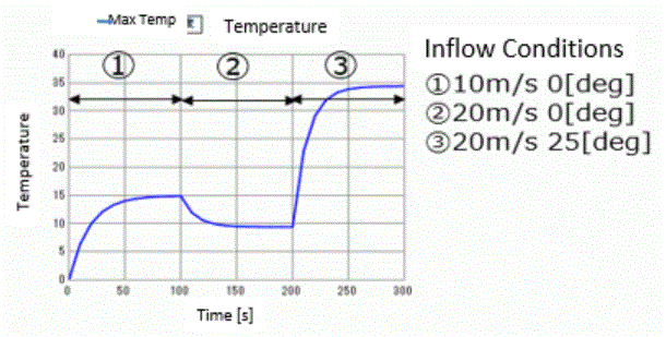
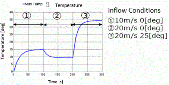
The inflow velocity and the inflow temperature are changed by the weight function as below.
(1)0[s]~100[s]: inflow velocity 10[m/s], inflow temperature 0[deg]
(2)101[s]~200[s]: inflow velocity 20[m/s], inflow temperature 0[deg]
(3)201[s]~300[s]: inflow velocity 20[m/s], inflow temperature 25[deg]
Results
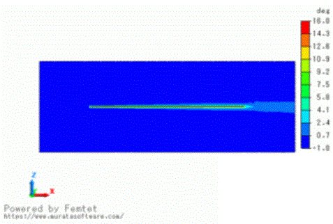
The temperature distribution after 100[s] is shown below.
The maximum temperature is 14.942 [deg].
Up to 100[s], the inflow velocity and the inflow temperature are the same as those of Example 2: Cooling of Plate by Forced Convection (Turbulent Flow).
Almost the same results as Example 2 are obtained.

Select [Temperature] of the table to show the graph.

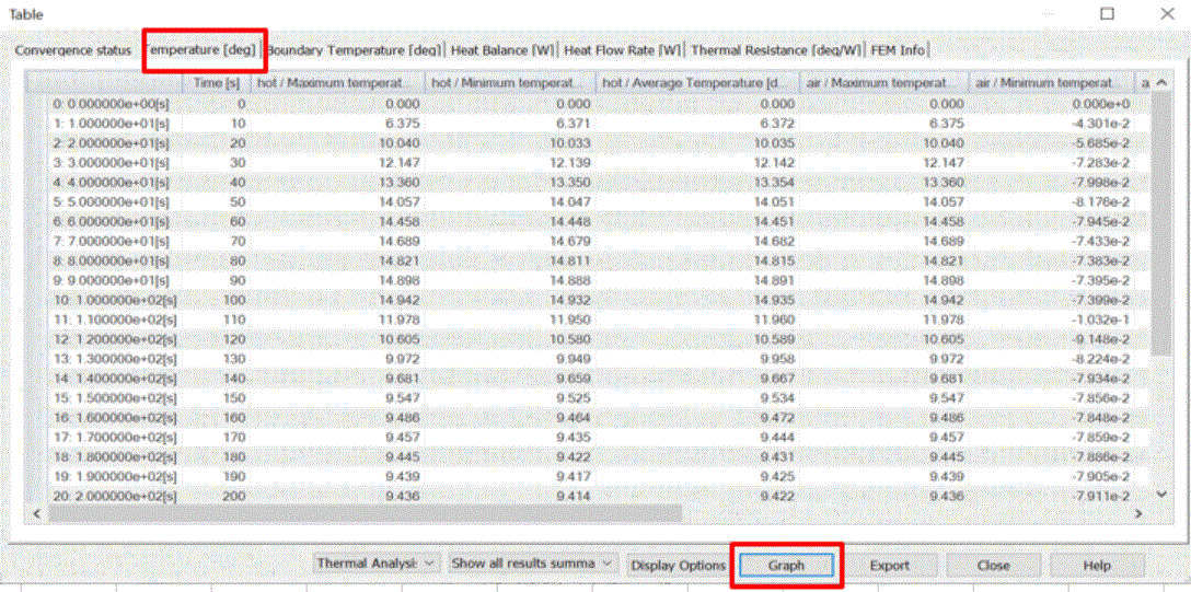
The graph below shows only hot/maximum temperature.
(Double click the graph to show the plot option. Deselect [Display Y-axis (primary axis)] except hot/maximum temperature.)
The temperature in the domain (2) goes down as the inflow velocity increases. The temperature in the domain (3) goes higher as the inflow temperature goes up.

