
CAE Software【Femtet】Murata Software Co., Ltd.
Example8 Transient Analysis of Cooling of IC with Initial Values Obtained in the Steady-state Analysis
General
-
After performing Example 6: Cooling of IC by Natural Convection, the IC is set OFF and temperature change is analyzed.
-
The temperature distribution and the heat flux vectors are solved.
-
Unless specified in the list below, the default conditions are applied.
Analysis Space
|
Item |
Setting |
|
Analysis Space |
3D |
|
Model Unit |
mm |
Analysis Condition (ic_board_trans_restart)
|
Item |
Setting |
|
Solver |
Fluid Analysis [Bernoulli] Thermal analysis [Watt] |
|
Analysis Type |
Fluid analysis: Transient analysis Thermal analysis: Transient analysis |
|
Laminar Flow/Turbulent Flow |
Select Turbulent Flow |
|
Initial Value/Restart |
Select Use another analysis results (Results Import) |
|
Options |
Select Take Buoyancy into Account (Natural Convection) |
|
Layer Mesh Setting for Wall Surface (General Settings) |
Parameters for Automatic Creation Expected Temperature Difference: 50[deg] |
|
Meshing Setup |
General Mesh size: 10 [mm] |
|
Tab |
Setting Item |
Setting |
||||||||
|
Transient Analysis |
Table |
|
|
Tab |
Setting Item |
Setting |
|
Results import |
Import Type |
Initial Values for Fluid-Thermal Analysis (By this setting, “Use another analysis result (Result Import)” is automatically selected on the Fluid-Thermal Analysis tab) |
|
Specify Results |
Specify analysis model: ic_board |
* Analysis model [ic_board] must be analyzed in advance.
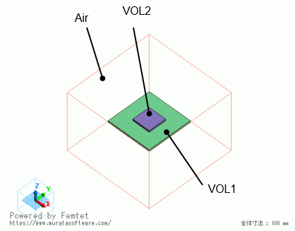
Model
The model is a box solid body. The material is Air (000_Air).
Set natural inflow/outflow to the outer boundary condition of Inlet/Outlet.
The substrate (VOL1) and IC (VOL2) are solid bodies.

Setting of Body Attributes, Materials, and Mesh Sizes
|
Body Number/Type |
Body Attribute Name |
Material Name |
Mesh Size |
|
0/Solid |
VOL1 |
006_Glass_epoxy * |
0.2 |
|
1/Solid |
VOL2 |
001_Alumina * |
0.2 |
|
2/Solid |
Air |
000_Air(*) |
– |
* Available from the material DB
IC (VOL2) is set as follows on the Heat Source tab. By setting 0W, the IC is set OFF.
|
Body Attribute Name |
Tab |
Setting |
|
VOL2 |
Heat Source |
0W |
Boundary Condition
|
Boundary Condition Name/Topology |
Tab |
Boundary Condition Type |
Setting |
|
Outer Boundary Condition |
Fluid-Thermal |
Inlet/Outlet |
Natural Inflow/Outflow Inflow temperature: Use ambient temperature (25[deg]) |
Results
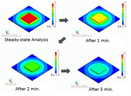
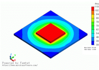
The figure below shows the temperature distribution after 0[s], 60[s], 180[s], and 300[s].
For easy viewing of the temperature distributions of the substrate and the IC, the ambient air field is hidden.
You can see the temperature of the IC goes down over time.
| Steady-state Analysis (0[s]) |
  |
| 1[min] |  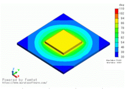 |
| 3[min] | 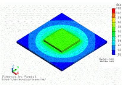  |
| 5[min] | 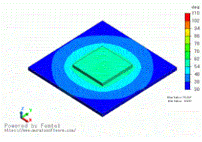  |