
CAE Software【Femtet】Murata Software Co., Ltd.
Example9 Cooling of IC inside a Case by Natural Convection (Closed Space and Open Space)
General
-
Heat dissipation of the IC by the natural convection is solved by the steady-state analysis. The IC is encased on the substrate.
-
The natural convections in the closed space of the case and in the open space outside the case are solved at the same time.
-
In [Example 10: Cooling of IC inside the Case by Natural Convection (Closed Space and Natural Convection Boundary Condition)],
the same problem is solved with one modification. In Example 10, the boundary condition of the surface of the casing is used and the analysis of the natural convection in the open space is omitted.
The analysis time will be reduced as the open space is not calculated. -
In [Example 15: Radiation and Cooling of IC inside a Case by Natural Convection (Closed Space and Open Space)],
radiation is taken into account as well. Compared to the natural convection alone, the temperature drop is large due to the heat dissipation by radiation.
-
The temperature distribution and the heat flux vectors are solved.
-
Unless specified in the list below, the default conditions are applied.
Analysis Space
|
Item |
Setting |
|
Analysis Space |
3D |
|
Model Unit |
mm |
Analysis Condition
|
Item |
Setting |
|
Solver |
Fluid analysis [Bernoulli] Thermal analysis [Watt] |
|
Analysis Type |
Fluid analysis: Steady-state analysis Thermal analysis: Steady-state analysis |
|
Laminar Flow/Turbulent Flow |
Select Turbulent Flow |
|
Option |
Select Take Buoyancy into Account (Natural Convection) |
|
Layer Mesh Setting for Wall Surface (General Settings) |
Parameters for Automatic Creation Expected Temperature Difference: 50[deg] |
|
Meshing Setup |
General Mesh size: 10 [mm] |
Model
The model is a box solid body. The material is Air (000_Air).
Set natural inflow/outflow to the outer boundary condition of Inlet/Outlet.
The substrate (VOL1), the IC (VOL2), and the case (CASE) are solid bodies.


Setting of Body Attributes, Materials, and Mesh Sizes
|
Body Number/Type |
Body Attribute Name |
Material Name |
Mesh Size |
|
0/Solid |
VOL1 |
006_Glass_epoxy * |
2.0 |
|
1/Solid |
VOL2 |
001_Alumina * |
2.0 |
|
2/Solid |
Air |
000_Air(*) |
– |
|
3/Solid |
CASE |
001_Al * |
4.0 |
* Available from the material DB
IC (VOL2) is set as follows on the Heat Source tab.
|
Body Attribute Name |
Tab |
Setting |
|
VOL2 |
Heat Source |
1W |
Boundary Condition
|
Boundary Condition Name/Topology |
Tab |
Boundary Condition Type |
Setting |
|
Outer Boundary Condition |
Fluid-Thermal |
Inlet/Outlet |
Natural Inflow/Outflow Inflow temperature: Use ambient temperature (25[deg]) |
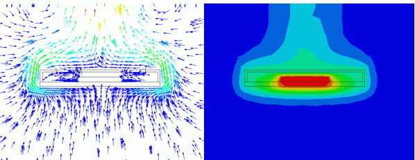
Results
The temperature distribution is shown below.
The cross section at x=0 is displayed.
There is a high-temperature area above the IC. You can observe the heat is transmitted mainly upward.
You can see the heat around the IC is higher than the other area.


By switching the solver type from thermal to fluid analysis, the flow velocity vectors are shown as below.
In the graphics setup, the 3D vector is set OFF and the vectors are set to the same length.
The small vectors less than 1mm/s are hidden.
Around the case, it is observed that the air heated by the case is moving upward.


The below is the enlarged figure of the inside of the case.
Although the flows are small compared to those around the case, the circulation is generated by the convection inside the case.

