CAE Software【Femtet】Murata Software Co., Ltd.

Example13 Heat Exchanger
General
-
A shell and tube heat exchanger is analyzed.
-
The temperature distribution and the heat flux vectors are solved.
-
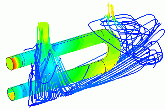
The results can be viewed by the simultaneous display of temperature contours and streamlines.
-
Unless specified in the list below, the default conditions will be applied.
Analysis Space
|
Item |
Setting |
|
Analysis Space |
3D |
|
Model Unit |
m |
Analysis Condition
|
Item |
Setting |
|
Solver |
Fluid analysis [Bernoulli] Thermal analysis [Watt] |
|
Analysis Type |
Fluid analysis: Steady-state analysis Thermal analysis: Steady-state analysis |
|
Meshing Setup |
General Mesh size: 0.03 [mm] Mesh size of the inside of inlet/outlet of the shell : 0.01[mm] |
Model
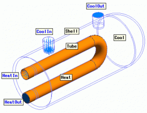
The coolant flows in the shell and the heat medium flows in the tube. The shell and the tube are made of solid body having thickness.
The coolant and the heat medium are air. The heat exchange takes place only through the tube of solid.

Body Attributes and Materials
|
Body Number/Type |
Body Attribute Name |
Material Name |
|
6/Solid |
Tube |
104_Stainless_steel * |
|
38/Solid |
Heat |
000_Air * |
|
45/Solid |
Shell |
104_Stainless_steel * |
|
46/Solid |
Cool |
000_Air * |
* Available from the material DB
Boundary Condition
|
Boundary Condition Name/Topology |
Tab |
Boundary Condition Type |
Setting |
|
CoolIn/Face |
Fluid-Thermal |
Inlet |
Specify flow velocity 1[m/s]
Fluid temperature Direct entry 20[deg] |
|
CoolOut/Face |
Fluid-Thermal |
Temperature |
Outlet Natural Outflow |
|
HeatIn/Face |
Fluid-Thermal |
Temperature |
Specify flow velocity 1[m/s]
Fluid temperature Direct entry 200[deg] |
|
HeatOut/Face |
Fluid-Thermal |
Temperature |
Outlet Natural Outflow |
Results
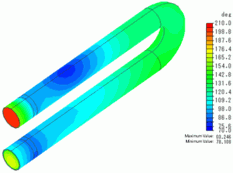
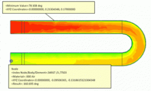
Fig. 1 shows the temperatures of the inside and the outside of the tube. The area where the coolant flows in and blows over the tube shows the lowest temperature.
The inlet temperature is 200 deg C and the outlet temperature is about 170 deg C, indicating that the heat exchange took place.
- Example 71 of Stress Analysis is conducted using this temperature distribution.


Fig. 1: Temperature Contour Diagram of Tube
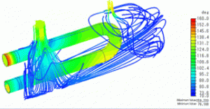
In Fig. 2, the coolant inside the shell is hidden. The temperature contours of the tube and the streamlines in the shell are simultaneously displayed.

Fig. 2: Temperature and Streamlines in Simultaneous Dispaly
