CAE Software【Femtet】Murata Software Co., Ltd.

Example12 Periodic Boundary Condition
General
-
The unit capacitors, consisting of alumina blocks and electrodes, are periodically placed in the analysis space.
-
By applying periodic boundary conditions, the analysis area can be minimized.
-
The distributions of electric field and potential are solved.
-
Unless specified in the list below, the default conditions will be applied.
Analysis Space
|
Item |
Settings |
|
Analysis Space |
3D |
|
Model unit |
mm |
Analysis Conditions
Select “Static analysis” as the potential is static.
|
Item |
Settings |
|
Solvers |
Electric Field Analysis [Coulomb] |
|
Analysis Type |
Static analysis |
|
Material Type |
Dielectric material |
|
Options |
N/A |
Create the ambient air manually. Deselect the automatic creation.
|
Tab |
Setting Item |
Settings |
|
Mesh Tab |
Ambient Air Creation |
Create ambient air automatically: Deselect |
Model
The base unit of the periodic structure is modeled.
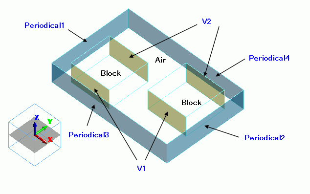
Body Attributes and Materials
|
Body Number/Type |
Body Attribute Name |
Material Name |
|
0/Solid |
Air |
000_Air(*) |
|
2/Solid |
Block |
001_Alumina * |
|
3/Solid |
Block |
001_Alumina * |
* Available from the Material DB
Boundary Conditions
|
Boundary Condition Name/Topology |
Tab |
Boundary Condition Type |
Settings |
|
V1/Face |
Electric |
Electric wall |
Voltage specified, 1[V] |
|
V2/Face |
Electric |
Electric wall |
Voltage specified, 0[V] |
|
Periodical1 |
Symmetry/Continuity |
|
Periodic |
|
Periodical2 |
Symmetry/Continuity |
|
Periodic |
|
Periodical3 |
Symmetry/Continuity |
|
Periodic |
|
Periodical4 |
Symmetry/Continuity |
|
Periodic |
On the [Model] tab,

click [Boundary Pair] ![]() and complete the pairing as follows.
and complete the pairing as follows.
|
List of Pairs |
|
Periodical1 – Periodical2 |
|
Periodical3 – Periodical4 |
Results
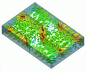
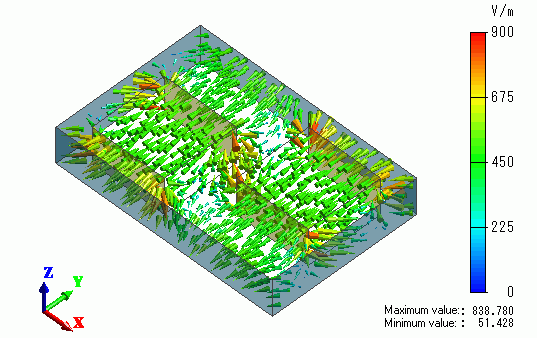
The vectors of the electric field are shown below.
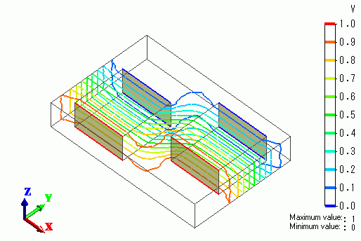
The isoline contour of the potential is shown below.
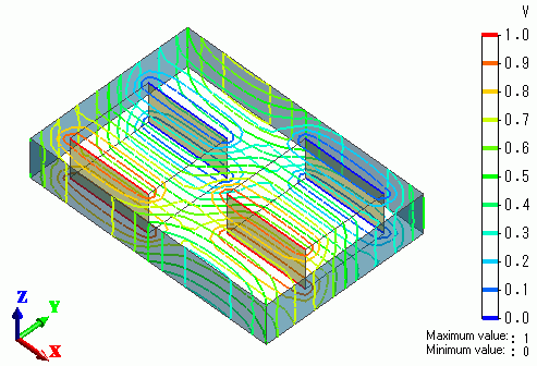
The paired faces of the periodic boundary conditions have the same values,
which proves that the solution is correct.
For comparison, the potential is calculated under the magnetic wall boundary condition.
The resulting isoline contour is shown below.
