CAE Software【Femtet】Murata Software Co., Ltd.

Example14 Harmonic Analysis of Conductor in the Air
General
-
Harmonic analysis is performed for the U-shaped conductor in the air.
-
The model’s equivalent resistance and capacitance are acquired.
-
Unless specified in the list below, the default conditions will be applied.
Analysis Space
|
Item |
Settings |
|
Analysis Space |
3D |
|
Model unit |
mm |
Analysis Conditions
|
Item |
Settings |
|
Solvers |
Electric Field Analysis [Coulomb] |
|
Analysis Type |
Harmonic analysis |
|
Options |
N/A |
The frequency of the applied voltage is set as belows.
|
Tab |
Setting Item |
Settings |
|
Harmonic analysis |
Frequency |
1×10^6[Hz] |
|
Sweep |
Select “Linear step by division number”. |
Model
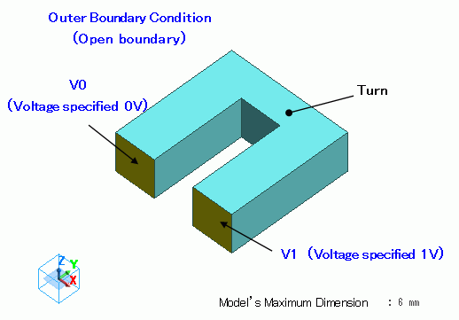
An U- shaped conductor is created with solid bodies.
Different electrical potentials are set on the ends of the U shape conductor.
Body Attributes and Materials
Select the aluminum for the material.
|
Body Number/Type |
Body Attribute Name |
Material Name |
|
1/Solid |
U |
008_Cu * |
* Available from the Material DB
Boundary Condition
The end faces of the U-shaped conductor are set with Electric wall boundary condition. They have different electrical potentials.
|
Boundary Condition Name/Topology |
Tab |
Boundary Condition Type |
Settings |
|
V0/Face |
Electric |
Electric wall |
Voltage specified, 0[V] |
|
V1/Face |
Electric |
Electric wall |
Voltage specified, 1[V] |
|
Outer Boundary Condition * |
Electric |
Magnetic wall |
|
To set Outer Boundary Condition, go to the [Model] tab

and click [Outer Boundary Condition] ![]() .
.
Results
To see the results, go to the [Results] tab,

click [Table] ![]() .
.
The calculated resistance is 5.797e-5[ohm] as shown below.
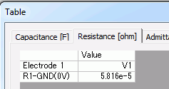
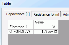
The calculated capacitance is 6.636e-14[F] as shown below.
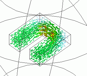
The vectors of the current density are shown below.
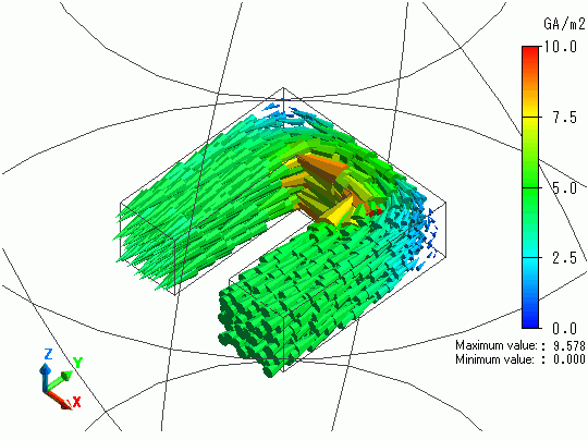
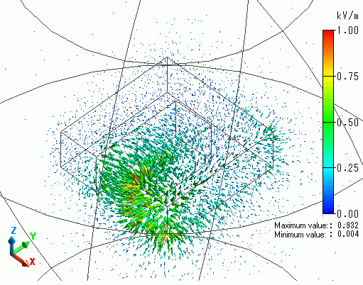
The vectors of the electric field are shown below.
