
CAE Software【Femtet】Murata Software Co., Ltd.
Example24 Mechanical Stress of a Tool
General
-
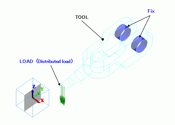
Two holes of a tool is fixed. The force is applied at the tip of the tool.
-
The deformation, the displacement and the mechanical stress are solved.
-
Unless specified in the list below, the default conditions will be applied.
Analysis Space
|
Item |
Settings |
|
Analysis Space |
3D |
|
Model unit |
mm |
Analysis Conditions
This is a static analysis.
|
Item |
Settings |
|
Solvers |
Mechanical Stress Analysis [Galileo] |
|
Analysis Type |
Static analysis |
|
Options |
N/A |
Model
The material is iron.
The inner faces of the holes are fixed by boundary condition.
The force is applied on the top face of the tool.
Body Attributes and Materials
|
Body Number/Type |
Body Attribute Name |
Material Name |
|
17/Solid |
TOOL |
007_Fe * |
* Available from the Material DB
Boundary Conditions
The force applied at the top face of the tool is assumed to be 980N (100kgf) in total and distributed uniformly on the face.
The area of the face: 0.0052×3.14=0.0000785m2
Distributed load: Total load / Tip area = approximately 12484076 N/m2(=Pa)
|
Boundary Condition Name/Topology |
Tab |
Boundary Condition Type |
Settings |
|
FIX/Face |
Mechanical |
Displacement |
Select all X/Y/Z components. UX=0, UY=0, UZ=0 |
|
LOAD/Face |
Mechanical |
Distributed face load |
X=0, Y=0, Z=-1.2×10^7[Pa] |
Results
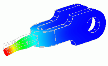
The displace diagram is shown below. The contour diagram shows the displacement.
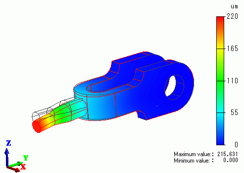
The displacement is larger towards the tip of the instrument.
The vectors of the mechanical stress are shown below.
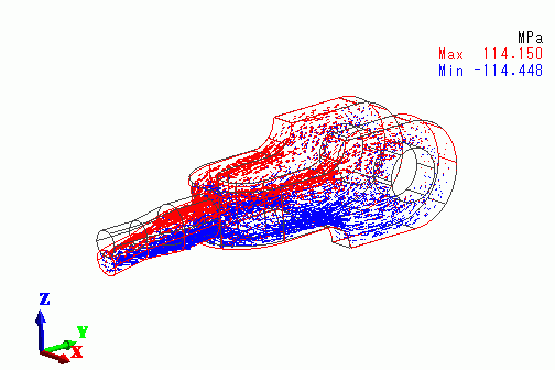
The upper part of the tool is getting the tensile stress, whereas the lower part is getting the compression stress.