CAE Software【Femtet】Murata Software Co., Ltd.

Example40 Deformation of Elasto-Plastic Multilinear Material
General
-
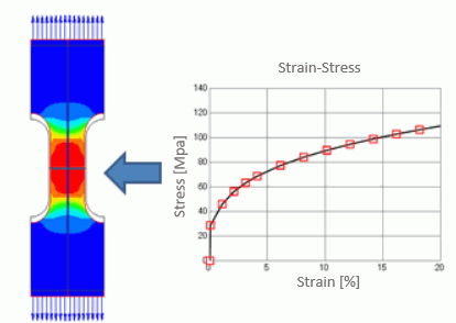
A plate inlaid with elasto-plastic multilinear material is deformed by forced displacement.
-
The deformation, the displacement and the mechanical stress are solved.
-
Unless specified in the list below, the default conditions will be applied.
Analysis Space
|
Item |
Settings |
|
Analysis Space |
Axisymmetric |
|
Model unit |
m |
Analysis Conditions
|
Item |
Settings |
|
Solvers |
Mechanical Stress Analysis [Galileo] |
|
Analysis Type |
Static analysis |
The nonlinear analysis is set up on the Step/Thermal Load tab as follows.
|
Tab |
Setting Item |
Settings |
|
Step/Thermal Load |
Step/Reached Temperature Setting |
Substeps of Step 1 : 10 |
|
Options for the Nonlinear Analysis |
Save the results of substeps : Select |
The default number of substeps is 20. It is adjusted to 10 in this exercise. Therefore the forced displacement applied on the top face is divided to 10 substeps and each substep is solved in order of precedence.
“Save results of substeps” is selected by default to see the results at all 10 steps.
Model
This model is axisymmetric. The axis of symmetry is Z-axis. The 3D body is actually a circular rod.
The body is made of the elasto-plastic multilinear material named “ML” and a forced displacement is applied on the top face of the body.
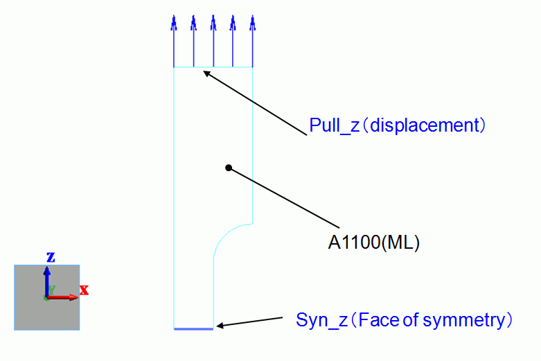
Body Attributes and Materials
|
Body Number/Type |
Body Attribute Name |
Material Name |
|
2/Sheet Body |
BA1 |
ML |
The material properties are set up as follows:
|
Material Name |
Tab |
Properties |
|
ML |
Elasticity |
Material Type: Elasto-plastic/Multilinear Young’s modulus: 69×10^9[Pa] Poisson’s ratio: 0.3
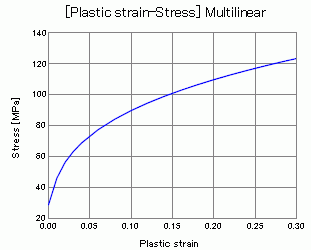
The plastic strain – stress multilinear curve of ML is shown bellow. This characteristic has been set on the “plastic strain – stress multilinear” table in the dialog box which appears when the button located in the “plastic strain – stress multilinear” area is clicked.
|
Boundary Condition
|
Boundary Condition Name/Topology |
Tab |
Boundary Condition Type |
Settings |
|
Sym_z/Edge |
Symmetry/Continuity |
Symmetry |
Select Reflective |
|
Pull_z/Edge |
Mechanical |
Displacement |
Select the Z component. UZ=0.2×10^-3[m] |
Results
The deformation at the step 1 is shown below.
The color contour shows the distribution of accumulated equivalent plastic strains.
[Full Model] is selected.
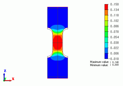
High strains are exhibited in the slim part of the body.
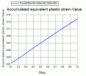
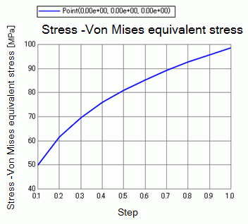
The charts below shows Accumulated equivalent plastic strain vs. Modes and von Mises equivalent stress vs. Modes at (0, 0, 0).
– Accumulated equivalent plastic strain
– Von Mises equivalent stress
A1100 (ML)’s plastic strain and Mises’s equivalent stress are plotted together for comparison.
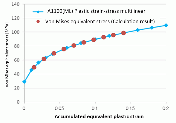
These plots match quite well.


