
CAE Software【Femtet】Murata Software Co., Ltd.
Example55 Rotational Displacement Analysis of Plate
General
-
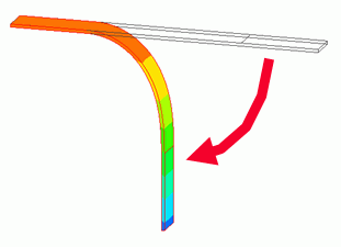
A plate bent in 90-degree angle is analyzed.
-
Analysis results will be compared where the option of [Rotate at constant radius] is selected and deselected for the Rotational displacement.
-
Unless specified in the list below, the default conditions will be applied.
Analysis Space
|
Item |
Settings |
|
Analysis Space |
3D |
|
Model unit |
mm |
Analysis Conditions
Select [Large displacement] in the Large Deformation as deformation of 90° is large.
|
Item |
Setting |
|
Solver |
Mechanical Stress Analysis [Galileo] |
|
Analysis Type |
Static analysis |
|
Large Deformation |
Select Large displacement |
The Step/Thermal Load tab is set as follows.
|
Tab |
Setting Item |
Setting |
|
Step/Thermal Load |
Options for the Multi-Step Analysis |
Save the results of substeps: Deselect |
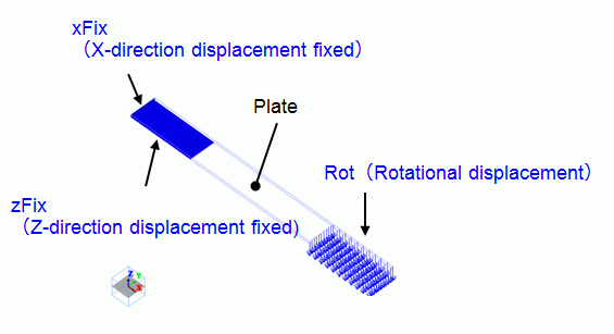
Graphical Objects
The model is a box solid body with edge length of 200mm. The material is iron.
Fix the left end in the X direction. Fix the 50mm area of the left end at its bottom in the Z direction.
The plate is bent at its center in 90-degree angle. Set the rotational displacement on the 50mm area of the right end at its top side.
Set the general mesh size at 2.
Body Attributes and Materials
|
Body Number/Type |
Body Attribute Name |
Material Name |
|
0/Solid |
PLATE |
007_Fe *1) |
|
1,2/Face |
No setup *2) |
No setup *2) |
*Note 1) Select from the Material DB.
*Note 2) Imprinting body for the boundary condition.
Boundary Condition
|
Boundary Condition Name/Topology |
Tab |
Boundary Condition Type |
Settings |
|
xFix/Face |
Mechanical |
Displacement |
Select the X Component. |
|
zFix/Face |
Mechanical |
Displacement |
Select the Z Component. |
|
Rot/Face |
Mechanical |
Rotational displacement |
Coordinates on the Axis Vectors of the Axis Rotation Angle Rotate at constant radius |
Results
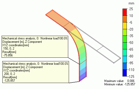
The deformation of the Model 1 is shown below. The contour diagrams show displacement in X direction and Z direction respectively.
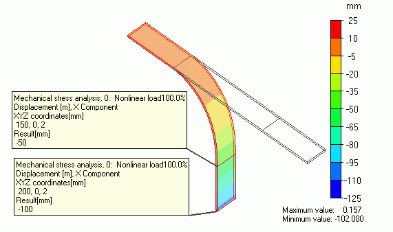
The displacement at the end and middle of the plate shows
-50 and -100 in the X direction as defined.
The displacement in the Z direction shows -75.856 and -125.857.
The results are larger than -50, and -100 in the case where the radius is constant. It indicates the radius changed during the rotation.
The reactive force at the boundary condition [Rot] in the table shows
almost 0 in the Y and Z directions and -798[N] in the X direction only.
If [Rotate at constant radius] is deselected, the force will be applied in the rotational direction during the rotation.
The deformation of the Model 2 is shown below. The contour diagrams below show displacement in X direction and Z direction respectively.
Unlike Model 1, the plate is bent in a complex way.
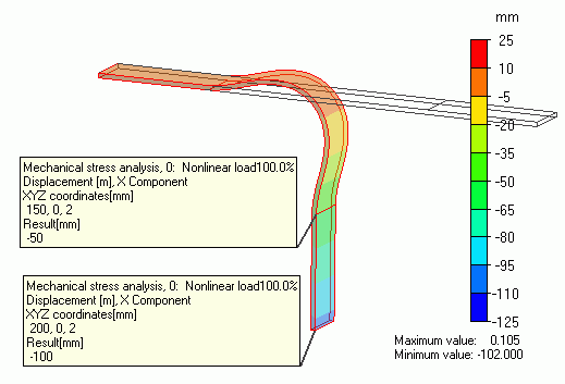
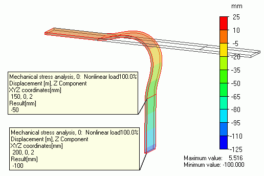
The displacement at the end and middle of the plate shows
-50 and -100 in the X direction as defined.
The displacement in the Z direction also shows -50 and -100.
It indicates the model is rotating at the constant radius.
The reactive force at the boundary condition [Rot] in the table shows
almost 0 in the Y direction and -4759[N] in the X direction and 4727[N] in the Z direction.
Unlike the Model 1, large force is taking place in the Z direction too.
If [Rotate at constant radius] is selected, a force is required to keep the radius constant.
Therefore, the force in Z direction is generated.