CAE Software【Femtet】Murata Software Co., Ltd.

Example59 Compression Analysis of O-Ring
General
-
O-ring is analyzed which is put between the upper metal plate and the groove of the lower metal plate.
-
As the material of O-ring is rubber, it is treated as hyperelastic material.
-
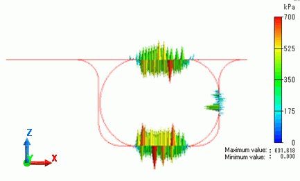
The deformation, the displacement and the mechanical stress, and contacting face pressure are solved.
-
Unless specified in the list below, the default conditions will be applied.
-
See [Analysis of Hyperelastic Materials] for more details.
Analysis Space
|
Item |
Setting |
|
Analysis Space |
Axisymmetric |
|
Model unit |
mm |
Analysis Conditions
To use hyperelastic material, select [Large displacement] in [Large deformation]
|
Item |
Setting |
|
Solver |
Mechanical Stress Analysis [Galileo] |
|
Analysis Type |
Static analysis |
|
Large Deformation |
Select Large displacement |
Set up as follows on the Step/Thermal Load tab.
Increase the number of substeps to 40 for stabilizing the analysis.
The results at the substeps are also output to show the intermediate results of compression.
|
Tab |
Setting Item |
Setting |
|
Step/Thermal Load |
Step/Reached Temperature Setting |
Substeps of Step 1 : 40 |
|
Options for the nonlinear analysis |
Select Save the results of substeps |
Graphical Objects
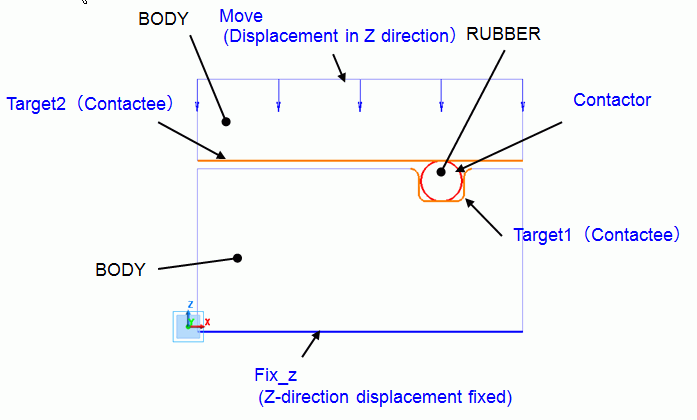
Create groove on the top face of lower BODY (metal plate).
Place RUBBER (O-ring) in the groove.
Place another BODY (metal plate) on top of the RUBBER.
Fix the bottom face of lower BODY in Z direction, and apply displacement in Z direction to the top face of upper BODY.
To take RUBBER and BODY into account, set the contactor on the RUBBER surface,
and contactee on the groove surface of the lower BODY and bottom face of the upper BODY.
Body Attributes and Materials
|
Body Number/Type |
Body Attribute Name |
Material Name |
|
2/Sheet |
RUBBER |
Natural_rubber |
|
3,4/Sheet |
BODY |
504_SUS304 (*) |
(*) Available from the Material DB
|
Material Name |
Tab |
Properties |
|
Natural_rubber |
Hyperelasticity |
Hyperelastic Model Type: Neo Hooke Shear Elastic Modulus: 3.92 x 10^5 [Pa] |
Boundary Conditions
The displacement and contacting faces are set.
|
Boundary Condition Name/Topology |
Tab |
Boundary Condition Type |
Setting |
|
Fix_z/Edge |
Mechanical |
Displacement |
Select the Z component |
|
Move/Edge |
Mechanical |
Displacement |
Select the Z component |
|
Contactor/Edge |
Mechanical |
Contact surface |
Contactor surface |
|
Target1,Target2/Edge |
Mechanical |
Contact surface |
Contactee surface |
The following contact pairs are set in “Boundary Pair” dialog.
|
Boundary Pair |
Coefficient of friction: |
|
Contactor-Target1 |
0.5 |
|
Contactor-Target2 |
0.5 |
Results
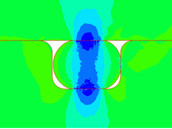
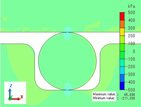
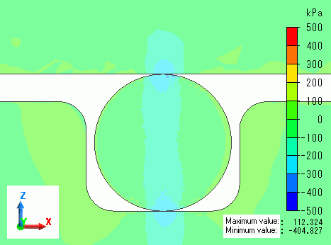
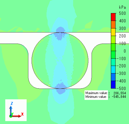
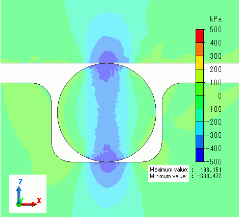
Deformation diagrams with load of 25%, 50%, 75%, and 100% are shown below. The contour indicates the Z normal stress.
You can observe the O-ring is deforming according to the load.
Load: 25%
Load: 50%
Load: 75%
Load: 100%
Vector diagram below shows contacting face pressure at the load of 100%.
At the load of 100%, faces contact at both sides as well as top and bottom. Contact face pressure at the side can be observed.
