
CAE Software【Femtet】Murata Software Co., Ltd.
Example3 Heating due to the Iron Loss
General
-
A coil is wound on a core. The heating due to the iron loss is analyzed.
-
The vectors of the magnetic field, the loss in the core, and the temperature distribution by the heating are solved.
-
Unless specified in the list below, the default conditions will be applied.
Analysis Space
|
Item |
Settings |
|
Analysis Space |
3D |
|
Model unit |
mm |
Analysis Conditions
|
Item |
Settings |
|
Solver |
Magnetic Field Analysis [Gauss] Thermal Analysis [Watt] |
|
Analysis Type |
Magnetic field analysis: Harmonic analysis Thermal analysis: Steady-state analysis |
|
Options |
N/A |
The frequency of the current is set to 50[kHz].
|
Tabs |
Setting Item |
Settings |
|
Mesh Tab |
Frequency-Dependent Meshing |
Reference frequency: 50×103[Hz] Surface Treatment for Conductors: Generate skin meshes |
|
Harmonic analysis |
Frequency |
Sweep Type: Single frequency Frequency: 50×103[Hz] |
Model
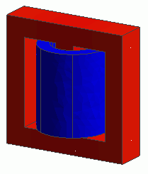
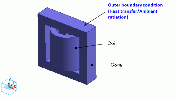
A coil is wound on a core.
The bodies of a core (Core) and a loop coil (Coil) are defined.
The automatically created ambient air is analyzed only in the magnetic field analysis, not in the thermal analysis.
Body Attributes and Materials
|
Body Number/Type |
Body Attribute Name |
Material Name |
|
5/Solid |
Coil2 |
008_Cu * |
|
7/Solid |
Coil1 |
008_Cu * |
|
6/Solid |
Core |
Core |
* Available from the Material DB
Body attribute is set up as follows to apply current to the loop coil.
|
Body Attribute Name |
Tab |
Settings |
|
Coil |
Current |
Waveform: AC Current: 0.1[A] Turns: 100[Turns] Induced current: No setting Direction: Loop Coil/Magnetic Field Direction Direction Vector of Magnetic Field: X=0, Y=0, Z=1 |
The material properties of the core are set up as follows. The loss is defined in the iron loss table.
|
Material Name |
Tab |
Settings |
|||||
|
Core |
Permeability |
Relative Permeability: 3000 |
|||||
|
Conductivity |
Conductivity Type: Conductor Conductivity: 0.1[S/m] |
||||||
|
Thermal Conductivity |
Thermal Conductivity: 10[W/m/deg] |
||||||
|
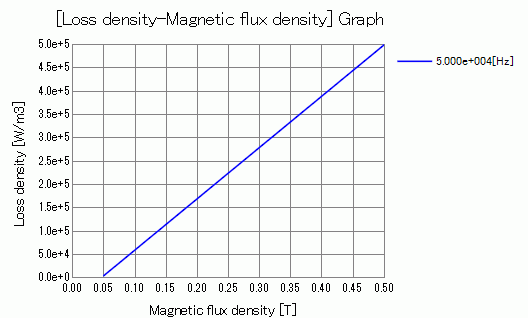
Iron loss |
Iron Loss Calculation Type: Iron loss table
Frequency: 5×10⁴[Hz] [Magnetic flux density-Loss density] Table *
* This is not the actual material’s property. |
Press the Graph button. The following graph will show up.
Boundary Conditions
“Natural convection (automatic calculation)” is set on the outer boundary condition (surrounding the coil and core in the case of the thermal analysis).
|
Boundary Condition Name/Topology |
Tab |
Boundary Condition Type |
Settings |
|
Outer Boundary Condition * |
Thermal |
Heat Transfer/Ambient Radiation |
Natural convection (automatic calculation) Ambient temperature: 25[deg] |
To set Outer Boundary Condition, go to the [Model] tab
and click [Outer Boundary Condition] ![]() .
.
* The correction coefficient for the natural convection is calculated automatically. See [Heat Transfer/Ambient Radiation] for more information.
Results
To see the iron loss, go to the [Results] tab

click [Table] ![]() .
.
The joule loss is shown below.
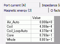
The iron loss is shown below.
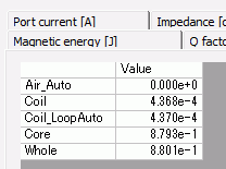
The core’s iron loss is approximately 0.9[W].
The joule loss and the hysteresis loss of the core are not given because the the material property is defined on the iron loss table.
The loss characteristics are defined in the iron loss table. Only iron loss is obtained.
If it is defined by the iron loss experimental formula, the joule loss and the hysteresis loss will be output as well.
See [Loss Calculation in the Magnetic Field Analysis] for details of the loss.
The vectors of the magnetic flux density are shown below.
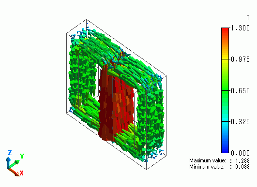
The flux density is looping through the core.
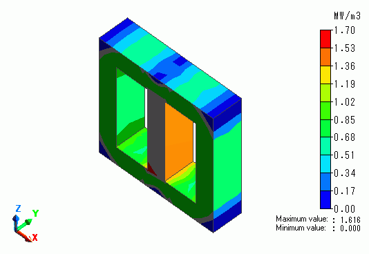
The iron loss density is shown below.
The temperature contour as a result of Watt is shown below.
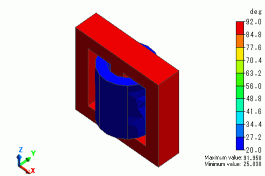
The core temperature goes up to around 90[deg].