CAE Software【Femtet】Murata Software Co., Ltd.

Example30 Dipole and Monopole Antennas

General
-
Dipole antenna’s characteristics are simulated for a full model, a half model, and a quarter model.
-
Analysis of monopole antenna having infinite ground is explained.
-
Unless specified in the list below, the default conditions will be applied.
-
Also see [Exercise 7: Dipole Antenna].
Analysis Space
|
Item |
Setting |
|
Analysis Space |
3D |
|
Model unit |
mm |
Analysis Conditions
|
Item |
Setting |
|
Solver |
Electromagnetic Analysis [Hertz] |
|
Analysis Type |
Harmonic Analysis |
|
Options: Correction coefficient for the characteristic impedance |
1.0 for dipole full or quarter model, and monopole antenna |
|
2.0 for dipole half model |
|
|
Options |
Select “Ignore the influence of face/edge electrode thickness” * |
* This is the default setting. It is irrelevant to select it or not as there are no face electrodes with this model.
Harmonic Analysis tab and Open Boundary tab are set as follows.
|
Tab |
Setting Item |
Setting |
|
Harmonic Analysis |
Frequency |
Minimum: 3×10^9[Hz] Maximum: 6×10^9[Hz] |
|
Sweep Type |
Select Linear step by division number. Division number: 100 |
|
|
Sweep Setting |
Select Fast sweep S-parameter tolerance: 1×10^-3 |
|
|
Input |
1.0[W] |
|
|
Open Boundary |
Type |
Absorbing boundary |
|
Order of Absorbing Boundary |
1st degree |
Graphical Objects
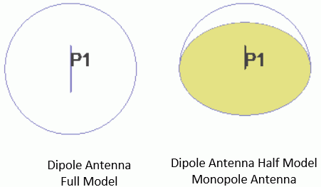
Dipole antenna’s full model, half model, and quarter model are shown below.
Monopole antennas is the same as the dipole antenna’s half model.
All models consist of copper ANTENNA body, AIR body, and port.
Dipole antenna’s full model is covered with a sphere of air.
Dipole antenna’s half model is covered with a hemisphere of air.
The flat face of hemisphere is on XY plane. It is set with electric wall boundary condition (EWall).
For the half model, this electric wall is a boundary condition indicating the symmetry.
The quarter model is created by cutting the half model with YZ plane.
The face on YZ plane is set with the magnetic wall boundary condition (MWall).
This magnetic wall is also a boundary condition indicating the symmetry.

-
Refer to the [Electric tab] for the electric wall and magnetic wall.
Body Attributes and Materials
|
Body Number/Type |
Body Attribute Name |
Material Name |
|
0/Solid |
ANTENNA |
008_Cu * |
|
3/Solid |
AIR |
000_Air(*) |
|
6/Sheet |
Imprinting body |
|
* Available from the Material DB
Boundary Conditions
|
Boundary Condition Name/Topology |
Tab |
Boundary Condition Type |
Setting |
|
EWall/Face |
Electric |
Electric wall |
|
|
MWall/Face |
Electric |
Magnetic wall |
|
|
PORT/Face |
Electric |
I/O Port |
Reference Impedance: Select “Specify” and enter 50[Ohm]. Number of Modes |
|
Outer Boundary Condition |
Electric |
Open boundary |
Select on the open boundary tab of the analysis condition setting. |
Set up Mesher/Solver
|
Setting Item |
Setting |
|
Frequency-Dependent Meshing |
Reference frequency: 5×10^10[Hz] |
The resonant frequency calculated from the antenna length is given for the reference frequency.
Result 1: Comparison of Results for the Dipole Antennas with Plane of Symmetry.
Dipole antenna’s characteristics obtained for a full model, a half model, and a quarter model are all matched.
Antenna’s reflection characteristics can be confirmed in the S-parameters and Smith chart of impedance.
Go to the [Results] tab. In the [Chart] ![]() , click [SYZ Matrix].
, click [SYZ Matrix].
In the [SYZ Matrix] dialog box, click [XY_Graph] or [SmithChart].
The corresponding graphs will appear.
-
For the details of [SYZ Matrix] dialog box, see [SYZ Matrix].
The reflection characteristics of the full model, half model, and quarter model are shown in the Figure 1.
They are all well matched.
|
|
|
Figure 1: The reflection characteristics of the dipole antenna’s full model, half model, and quarter model |
Next, we will see the directivity which represents the antenna’s radiation pattern.
Go to the [Results] tab. In the [Chart] ![]() , click [Directivity].
, click [Directivity].
In the [Directivity Calculation] dialog box, set the [Electromagnetic Waves Directivity] tab as in the Table 1.
Set Plane of Symmetry and Infinite Ground Plane according to the models as in the Table 2.
Click [Polar Graph], and a polar graph showing directivity like Figure 2 will appear.
-
For the details of the [Electromagnetic Waves Directivity] tab, refer to [Electromagnetic Waves Directivity].
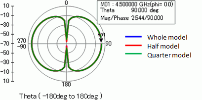
The directivity of the full model, half model, and quarter model are shown in the Figure 2.
Comparison is done at 4.5GHz where the reflection is small.
Radiation patterns are well matched too.
Table 1: Setting of [Electromagnetic Waves Directivity] tab
|
Tab |
Setting Item |
Setting |
|
Electromagnetic Waves Directivity |
Frequency |
4.500000 GHz |
|
Observation point |
φ |
|
|
θ |
||
|
Display Type |
POWER |
|
|
Unit |
dBi |
|
|
Plane of Symmetry and Infinite Ground Plane |
Refer to Table 2. |
|
|
Setup |
Horizontal axis: θ |
|
|
Other |
Table 2: Setting of plane of symmetry and infinite ground plane
|
Model |
XY plane |
YZ plane |
ZX plane |
|
Dipole Antenna Full Model |
Asymmetric |
Asymmetric |
Asymmetric |
|
Dipole Antenna Half Model |
Electric wall |
Asymmetric |
Asymmetric |
|
Dipole Antenna Quarter Model |
Electric wall |
Asymmetric |
Magnetic wall |
|
Monopole Antenna |
Infinite ground plane |
Asymmetric |
Asymmetric |
|
|
|
Figure 2: The radiation pattern of the dipole antenna’s full model, half model, and quarter model |
Result 2: Analysis of Monopole Antenna Having Infinite Ground
Characteristics of the monopole antenna having infinite ground is analyzed.
Comparison is done with a half model of dipole antenna.
First, compare the reflection characteristics of the two antennas.
S-parameters and Smith chart are obtained as in the Figure 3.
The Figure 3 shows that the frequency is 4.59GHz where the imaginary part of impedance is close to 0.
Impedance Z of each antenna at this frequency are as follows.
-
Dipole Antenna: Z = 64.019 + j 0.159 [Ω]
-
Monopole Antenna: Z = 31.334 + j 1.883 [Ω]
Monopole antenna’s impedance is half of dipole antenna’s.
This means that when the same current flows in the dipole antenna and monopole antenna,
the voltage applied to the monopole antenna is half of that to the dipole antenna.
It can be considered to be a reasonable result.
|
|
|
Figure 3: Reflection characteristics of dipole antenna (half model) and monopole antenna |
Next, the radiation patterns will be compared.
In the [Directivity Calculation] dialog box, set the [Electromagnetic Waves Directivity] tab as in the Tables 3 and 4.
A directivity graph like Figure 4 will be obtained.
The Figure 4 shows monopole antenna’s gain is higher than dipole antenna’s by 3dB.
Table 3: [Electromagnetic Waves Directivity] tab setting
|
Tab |
Setting Item |
Setting |
|
Electromagnetic Waves Directivity |
Frequency |
4.590000 GHz |
|
Observation point |
φ |
|
|
θ |
||
|
Display Type |
POWER |
|
|
Unit |
dBi |
|
|
Plane of Symmetry and Infinite Ground Plane |
Refer to Table 2. |
|
|
Setting |
Horizontal axis: θ |
|
|
Other |
Table 4: Setting of plane of symmetry and Infinite ground plane
|
Model |
XY plane |
YZ plane |
ZX plane |
|
Dipole Antenna Half Model |
Electric wall |
Asymmetric |
Asymmetric |
|
Monopole Antenna |
Infinite ground plane |
Asymmetric |
Asymmetric |
|
|
|
Figure 4: Radiation pattern of dipole antenna (half model) and monopole antenna |


