CAE Software【Femtet】Murata Software Co., Ltd.
Example33 Propagation Mode in the Waveguide
General
-
The Frequency characteristics of the waveguide are analyzed.
-
Specific propagation mode can be selected for the analysis.
In this exercise, only TE20 will be analyzed.
The frequency will be changed from 10GHz to 20GHz at the 1GHz interval.
-
Step 1 is for obtaining the waveguide mode number of TE20.
Step 2 is for analysis of TE20.
First, the common settings for Steps 1 and 2 will be explained.
Then, Steps 1 and 2 will be explained individually.
-
S-parameters and the electromagnetic field distribution will be obtained.
Common Settings
The common settings for Steps 1 and 2 are explained.
Analysis Space
|
Item |
Setting |
|
Analysis Space |
3D |
|
Model unit |
mm |
Analysis Conditions
|
Item |
Setting |
|
Solver |
Electromagnetic Analysis [Hertz] |
|
Analysis Type |
Harmonic Analysis |
|
Options |
Select “Ignore the influence of face/edge electrode thickness” * |
* This is the default setting.
There will be no effect if this option is deselected because there are no face electrodes in this exercise.
The harmonic analysis is set as follows.
|
Tab |
Setting Item |
Setting |
|
Mesh |
Element type |
2nd-order element |
|
Multigrid/Adaptive Mesh Method |
Select “Use the adaptive mesh method”. |
|
|
Frequency-Dependent Meshing |
Reference frequency: 20×10^9[Hz] Select “The conductor bodies thicker than the skin depth constitute the boundary condition.”
There are no conductive solid bodies in this analysis model. Therefore the setting above is irrelevant. |
Graphical Objects
The waveguide is created as a box-shape solid body.
Set the I/O port boundary condition on both ends of the waveguide body (WAVEGUIDE).
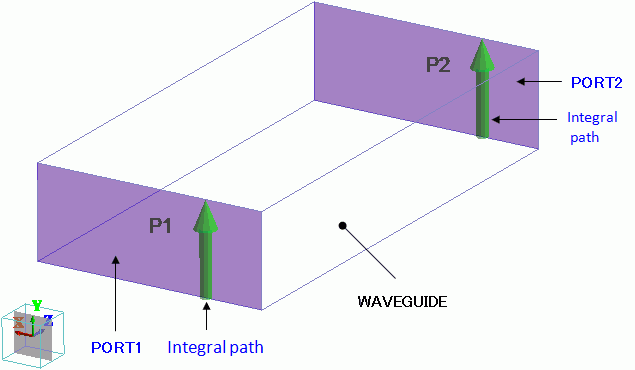
An integration path is set up on each I/O port.
The integral path has a function to specify the direction of electric field at 0-degree phase generated at the port.
The phase is 0 degree when the magnitude of electric field near the integral path is maximum in the direction of the integral path.
If the ports have no integral paths, results could be given where each port has different direction of 0-degree phase.
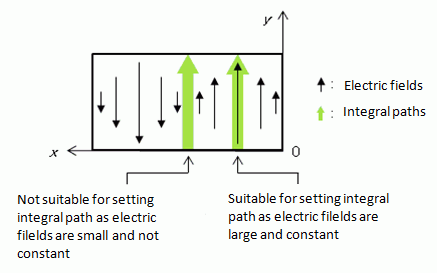
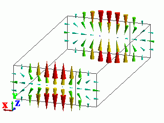
In this exercise, analysis object TE20 has electric field distribution as follows.
So the integral path is placed not in the center but to the side of the port where the electric fields are in the same direction.
Body Attributes and Materials
|
Body Number/Type |
Body Attribute Name |
Material Name |
|
0/Solid |
WAVEGUIDE |
000_Air(*) |
(*) Available from the Material DB
Boundary Conditions
|
Boundary Condition Name/Topology |
Tab |
Boundary Condition Type |
Setting |
|
Outer Boundary Condition |
Electric |
Electric wall |
|
Step 1: Identify the Waveguide Analysis Mode Number
In the electromagnetic waves analysis, two kinds of numbers are assigned to one propagation mode.
One is waveguide analysis mode number and the other is waveguide mode number (waveguide mode number in 3D analysis).
When necessary, either number will be used to identify the propagation mode.
To analyze specific propagation mode, waveguide analysis mode number will be used.
-
For details of the waveguide analysis mode number and the waveguide mode number,
see []How to Examine the Ports of Electromagnetic Analysis.
Analysis Conditions
Adding to the common settings, the analysis condition for Step 1 is set as follows.
In Step 1, it is required to use the maximum frequency of all frequencies of the target propagation mode for analysis.
In this exercise, analysis of TE20 mode is to be performed from 10GHz to 20GHz.
In the Step 1, therefore, the analysis is done with the maximum frequency of 20GHz.
|
Tab |
Setting Item |
Setting |
|
Electromagnetic Analysis |
Hertz Option |
Select Execute the waveguide analysis only |
|
Harmonic Analysis |
Frequency |
20×10^9[Hz] |
|
Sweep Type |
Select Single frequency |
|
|
Sweep Setting |
Discrete sweep* |
|
|
Input |
1.0[W] |
|
|
Deselect Enable each port’s individual weight setting for the superposed field display |
||
* As the analysis is performed with single frequency, any setting in Sweep Setting will have the same effect as discrete sweep.
Boundary Conditions
Adding to the common settings, each boundary condition for Step 1 is set as follows.
|
Boundary Condition Name/Topology |
Tab |
Boundary Condition Type |
Setting |
|
PORT1/Face |
Electric |
I/O Port |
Reference Impedance: Number of Modes |
|
PORT2/Face |
Electric |
I/O Port |
Reference Impedance: Number of Modes |
Results
The electric field vectors at port and the propagation constant are shown for each of 5 calculated modes as follows.
The propagation modes are also shown.
From the shape of electric field, you can see that “1: 2.000000e+010Hz: (1)” is TE20.
The waveguide analysis mode number of TE20 is “1” which is shown in parentheses at the end of the frequency.
|
Mode |
Electric Field Vectors |
Propagation Constant |
Propagation Mode |
|
0: 2.000000e+010Hz: (0) |
|
Port Name (phase constant) – j(attenuation constant) |
TE10 |
|
1: 2.000000e+010Hz: (1) |
|
Port Name (phase constant) – j(attenuation constant) |
TE20 |
|
2: 2.000000e+010Hz: (2) |
|
Port Name (phase constant) – j(attenuation constant) |
TE01 |
|
3: 2.000000e+010Hz: (3) |
|
Port Name (phase constant) – j(attenuation constant) |
TE11 |
|
4: 2.000000e+010Hz: (4) |
|
Port Name (phase constant) – j(attenuation constant) |
TM11 |
&n bsp;
-
If a propagation mode of your wish is not included in the calculated modes,
increase the Number of precalculated modes and redo the analysis.
-
If “NG” is shown on the propagation constant of your wish,
such propagation mode cannot be used in the 3D analysis.
For Number of modes used in the actual analysis, apply a larger number than the waveguide analysis mode number with “NG” notation.
Redo the analysis, and the “NG” notation will disappear.
The port number and the waveguide mode number (pxmy) will be shown.
From the calculation above, the waveguide analysis number of TE20 is identified as 1.
Step 2: Analyze the Selected Propagation Mode
Analysis Conditions
Analysis conditions set in the Step 1 are changed for the Step 2 as follows.
|
Tab |
Setting Item |
Setting |
|
Electromagnetic Analysis |
Hertz Option |
Deselect Execute the waveguide analysis only. |
|
Harmonic Analysis |
Sweep |
Minimum frequency : 10×10^9[Hz] |
|
Sweep Type |
Select “Linear step by frequency” |
|
|
Sweep Setting |
Fast sweep |
|
|
Input |
1.0[W] |
|
|
Select Enable each port’s individual weight setting for the superposed field display |
||
Boundary Conditions
The boundary conditions are changed as follows.
In “Select modes”, select the waveguide analysis mode number which you want to analyze.
Select mode01 in “Select modes” as the waveguide analysis mode number of TE20 is 1.
|
Boundary Condition Name/Topology |
Tab |
Boundary Condition Type |
Setting |
|
PORT1/Face |
Electric |
I/O Port |
Reference Impedance: Number of Modes |
|
PORT2/Face |
Electric |
I/O Port |
Reference Impedance: Number of Modes |
-
The number of modes shown in Select modes indicate
the Number of precalculated modes.
If the waveguide analysis mode number of your wish is not shown,
change the Number of precalculated modes.
Result 1: Fields
Examine the fields where TE20 enters from PORT1 as follows.
Identify the waveguide mode number of the propagation mode which you want.
Set up the fields viewing of the propagation mode using the waveguide mode number.
First, identify the waveguide mode number of TE20.
On the [Results] tab, select Port in [Solver type]. From the maximum frequencies in [Mode],
select the mode with waveguide analysis mode number 1 which represents TE20.[Propagation Constant] dialog box will appear.
x and y in the notation of [pxmy] indicate the port number and the waveguide mode number respectively.
At the maximum frequency of 20GHz, the mode “51: 2.000000e+010Hz:(1)” with the waveguide analysis mode number 1
shows the propagation constant as follows. From this, you can see the waveguide mode number of TE20 is “1”.
|
Propagation Constant |
|
Port Name (phase constant) – j(attenuation constant) PORT1 p1m1: 3.355935e+002 +j 0.000000e+000 PORT2 p2m1: 3.355964e+002 -j 2.527736e-027 |
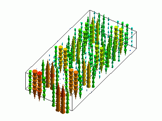
The setting for viewing the field of TE20 is as follows.
Go to the [Results] tab. For [Sover], select Electromagnetic waves analysis, and click [Field Superposition Setting].
MAG and PHASE can be set for each propagation mode at the port.
PortName and y in the notation of [PortName: my] indicate the boundary condition name of port and the waveguide mode number respectively.
To view the fields where TE20 enters PORT1, set MAG of PORT1:m2 to “1”,
and set other MAG and PHASE to “0”.
Select the frequency and field of your wish in [Mode] and [Field] respectively.
The field can be viewed where TE20 enters PORT1.
-
To view the fields where TE20 enters PORT1, set MAG of PORT2:m1 to “1”.
For the details of [Field Superposition Setting], see[Field Superposition Setting].
With the set up in the [Field Superposition Setting] dialog box as below,
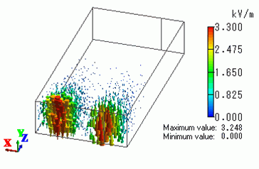
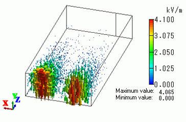
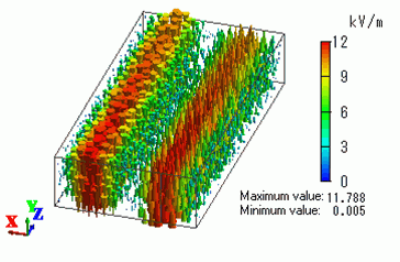
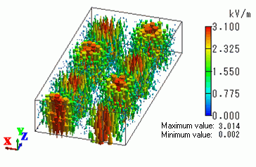
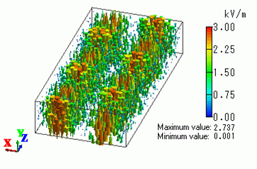
electric field vector diagrams of some modes (frequencies) are shown.
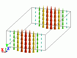
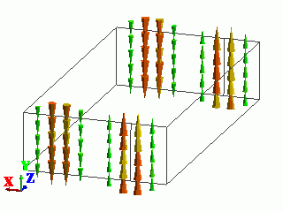
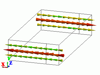
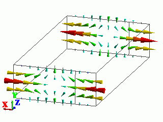
As seen in the electric field vector diagrams, if a frequency is lower than 12GHz,
TE20 entering PORT1 is not transmitting to PORT2.
|
Port Name |
MAG |
PHASE[deg] |
|
PORT1:m1 |
1.0 |
0.0 |
|
PORT2:m2 |
0.0 |
0.0 |
|
Mode |
Electric Field Vector Diagram |
|
0: 10.000000 GHz |
|
|
1: 11.000000 GHz |
|
|
2: 12.000000 GHz |
|
|
6: 16.000000 GHz |
|
|
10: 20.000000 GHz |
|
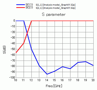
Result 2: S-parameters
Examine the S-parameters of the waveguide.
Go to [Results] tab. Click [Charts] and select SYZ Matrix.
In the [SYZ Matrix] dialog box, Port Index shows the numbers indicating the correspondence with
port and propagation mode in the S-parameters.
Now, the Port Index shows as below.
|
Port Index |
|
1: PORT1:m1 |
In this exercise, the waveguide mode number 1 (m1) indicates TE20.
Therefore, each of four S-parameters has the meaning as follows.
-
S(1, 1): The ratio of incident wave of TE20 to PORT1 and reflecting wave of TE20 at PORT1 when there is no incident wave to PORT2
-
S(1, 2): The ratio of incident wave of TE20 to PORT2 and transmitting wave of TE20 to PORT1 when there is no incident wave to PORT1
-
S(2, 1): The ratio of incident wave of TE20 to PORT1 and transmitting wave of TE20 to PORT2 when there is no incident wave to PORT2
-
S(2, 2): The ratio of incident wave of TE20 to PORT2 and reflecting wave of TE20 at PORT2 when there is no incident wave to PORT1
In the [SYZ Matrix] dialog box, select (1,1) and (2,1) for Matrix Elements and click [XY_Graph].
An S-parameters graph will appear as follows.
At the frequencies lower than 12GHz, TE20 transmits to PORT2 from PORT1 in small degree whereas it is larger at the higher frequencies than 12GHz.
S-parameters support the result obtained from the electric field vector diagrams.