CAE Software【Femtet】Murata Software Co., Ltd.

Example42 Wireless Power Transfer Using Electromagnetic Resonance

General
-
The wireless power transfer using electromagnetic resonance with the open-end coils is analyzed.
-
The open boundary for low frequency analysis is used to improve the accuracy.
-
Unless specified in the list below, the default conditions will be applied.
Analysis Space
|
Item |
Setting |
|
Analysis Space |
3D |
|
Model Unit |
m |
Analysis Condition
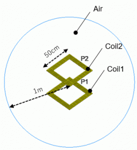
Since the wavelength of the analysis frequency (25m) is much larger than the size of self-resonant coil (50 square cm), the absorbing boundary used for low frequency analysis is applied as an open boundary type.
|
Item |
Setting |
|
Solver |
Electromagnetic analysis [Hertz] |
|
Analysis Type |
Harmonic analysis |
|
Tab |
Setting Item |
Setting |
|
Open Boundary |
Type |
Absorbing boundary (low frequencies) |
|
Mesh |
Frequency-Dependent Meshing |
Reference frequency: 12[GHz] Select The conductor bodies thicker than the skin depth constitute the boundary condition |
|
Harmonic Analysis |
Sweep Type |
Select “Linear step by division number” |
|
Sweep Setting |
Minimum frequency: 11[MHz] Maximum frequency: 13[MHz] Division number: 200 |
|
|
Frequency Sweep |
Select Fast sweep S-parameter tolerance: 1×10⁻³ |
Model
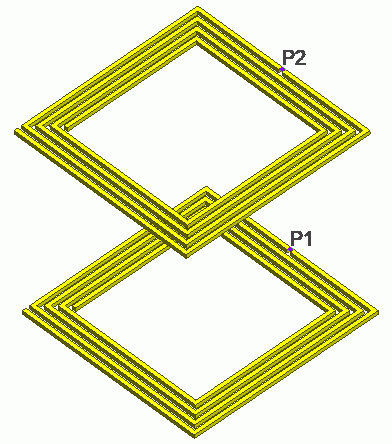
The model consists of two open-end coils (Coil1 and Coil 2) and spherical air (Air).
The coils self resonate at around 12MHz. The size of the air domain is 2m in diameter that is much smaller than the wavelength at the self resonant frequency (25m).


Body Attributes and Materials
|
Body Number/Type |
Body Attribute Name |
Material Name |
|
1, 2/Solid |
Coil1 |
008_Cu (*) |
|
3/Solid |
Air |
000_Air * |
|
4, 5/Solid |
Coil2 |
008_Cu (*) |
* Available from the material DB
Boundary Condition
|
Boundary Condition Name/Topology |
Tab |
Boundary Condition Type |
Setting |
|
Port1/Face |
Electric |
Port |
Reference impedance:
Integral path Set Path1 |
|
Port2/Face |
Electric |
Port |
Reference impedance:
Integral path Set Path1 |
|
Outer Boundary Condition |
Electric |
Open boundary |
|
Set up Mesher/Solver
|
Setting Item |
Setting |
|
Frequency-Dependent Meshing |
Reference frequency: 12[GHz] Select The conductor bodies thicker than the skin depth constitute the boundary condition |
Results
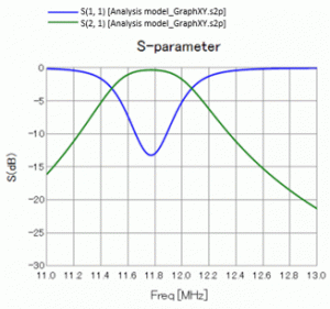
The open-end coils (Coil1 and Coil2) are designed to self resonate at around 12MHz. From the S-parameters in the diagram below, it can be confirmed that they resonate at around 12MHz.


At around 12MHz, S21 is larger than S11, indicating that the power from Port1 is mostly transferred to Port2.
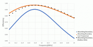
The efficiency is plotted (orange color) in the graph below with the following equation.
Efficiency = |S21| 2/ (1 – |S11|2)


In the graph, the result (blue color) of the conventional absorbing boundary is compared with the result (black color) of the absorbing boundary set at a sufficient distance of 10m from the wave source.
The wavelength of the analysis frequency is about 25m. The open boundary is located near the port, which is a wave source, at a distance of about 1m.
With the conventional absorbing boundary, the accuracy of the open boundary that is too close to the wave source is low. Consequently, the conventional absorbing boundary (blue) and the open boundary for low frequencies (orange)
show the difference in results.
By comparing with the result (black) where the absorbing boundary is set at a sufficient distance from the wave source, it is clear that the open boundary for low frequencies analysis achieves
highly accurate open boundary even though it is close to the wave source.

