CAE Software【Femtet】Murata Software Co., Ltd.

Example1 TM-Mode Dielectric Resonator

General
-
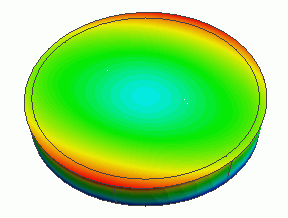
The model is a TM-mode dielectric resonator.
-
It is analyzed by the electromagnetic waves-thermal-mechanical stress analysis.
-
Unless specified in the list below, the default conditions will be applied.
Analysis Space
|
Item |
Settings |
|
Analysis Space |
3D |
|
Model unit |
mm |
Analysis Conditions
|
Item |
Settings |
|
Solver |
Electromagnetic Analysis [Hertz] Thermal Analysis [Watt] Mechanical Stress Analysis [Galileo] |
|
Analysis Type |
Electromagnetic waves analysis: Resonant analysis Thermal analysis: Steady-state analysis Mechanical stress analysis: Static analysis |
|
Options |
Select “Ignore the influence of face/edge electrode thickness” * |
* This is the default setting. There are no face electrodes with this model. Therefore it is irrelevant to select it or not.
xx
* “Thermal Load” is selected by default for the thermal load-mechanical stress coupled analysis.
The resonant analysis is set up as follows.
|
Tabs |
Setting Item |
Settings |
|
Mesh Tab |
Mesh Size |
2.0 |
|
Element type |
2nd-order element |
|
|
Adaptive mesh |
Off (to shorten the calculation time) |
|
|
Frequency-Dependent Meshing |
Reference frequency: 1.0×10^9[Hz] |
|
|
Resonant analysis |
Number of modes |
3 |
|
Input power |
10[W] * |
|
|
Calculate the Q factor with high accuracy |
Select |
* The losses in electrodes and dielectric material are taken into account.
Therefore, all the input power is to be consumed in the resonator.
Model
Electrodes are set on the top and bottom faces of the dielectric disc.
The temperature and the displacement are fixed at the bottom electrode.

Body Attributes and Materials
|
Body Number/Type |
Body Attribute Name |
Material Name |
|
0/Solid |
Dielectric material |
Dielectric material |
|
1/Solid |
Electrode |
008_Cu * |
|
2/Solid |
Electrode |
008_Cu * |
* Available from the Material DB
|
Material Name |
Tab |
Properties |
|
Dielectric material |
Permittivity |
Relative Permittivity: 40 tanD: 0.001 |
|
Thermal Conductivity |
10[W/m/deg] |
|
|
Coefficient of Expansion |
10×10^-6[1/deg] |
|
|
Elasticity |
Young’s modulus: 1×10^9[Pa] |
Boundary Conditions
|
Boundary Condition Name/Topology |
Tab |
Boundary Condition Type |
Settings |
|
Bottom/Face |
Thermal |
Temperature |
25[deg] |
|
Mechanical |
Displacement |
Select UX, UY, and UZ all. The displacement is 0[m] for all. |
Results
The vectors of the electric fields resulting from the electromagnetic waves analysis [Hertz] are shown below.
Mode 0:

Mode 1:

The electric field in the center is peaked and bottomed in Modes 0 and 1 respectively.
The next figures show the results of thermal analysis [Watt].
Mode 0:

Mode 1:

The temperature rise is high at the area where the electric field is concentrating.
It is dependent on the distribution of the electromagnetic field.
The next figure shows the vectors of displacement as a result of Galileo following Watt.
Mode 0:

Mode 1:

The deformation is dependent on the distribution of the electromagnetic field.

