CAE Software【Femtet】Murata Software Co., Ltd.

Example10 Natural Convection with Correction Coefficient Manually Calculated

General
-
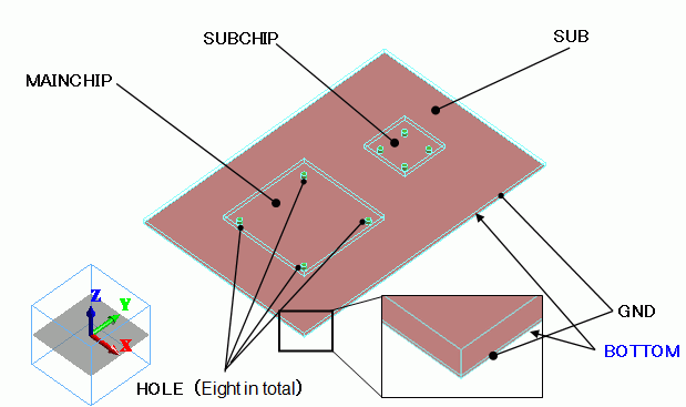
Two heat sources are placed on a substrate. Some heat is conducted to the bottom of the substrate through via holes.
The heat is released to the ambient by natural convection. The steady-state analysis is performed.
-
The temperature distribution and the heat flux vectors are solved.
-
Unless specified in the list below, the default conditions will be applied.
Analysis Space
|
Item |
Settings |
|
Analysis Space |
3D |
|
Model unit |
mm |
Analysis Conditions
|
Item |
Settings |
|
Solvers |
Thermal Analysis [Watt] |
|
Analysis Type |
Steady-state analysis |
|
Options |
N/A |
Model

Body Attributes and Materials
The finer mesh size is set for via holes (HOLE), where the heat flux is expected to change drastically.
|
Body Number/Type |
Body Attribute Name |
Material Name |
Mesh Size |
|
0/Solid |
SUB |
006_Glass_epoxy * |
|
|
1/Solid |
GND |
008_Cu * |
|
|
2/Solid |
MAINCHIP |
001_Alumina * |
|
|
3/Solid |
SUBCHIP |
001_Alumina * |
|
|
4/Solid |
HOLE |
008_Cu * |
0.5 |
|
5/Solid |
HOLE |
008_Cu * |
0.5 |
|
6/Solid |
HOLE |
008_Cu * |
0.5 |
|
7/Solid |
HOLE |
008_Cu * |
0.5 |
|
8/Solid |
HOLE |
008_Cu * |
0.5 |
|
9/Solid |
HOLE |
008_Cu * |
0.5 |
|
10/Solid |
HOLE |
008_Cu * |
0.5 |
|
11/Solid |
HOLE |
008_Cu * |
0.5 |
* Available from the Material DB
The heat sources of MAINCHIP and SUBCHIP are set up as follows.
|
Body Attribute Name |
Tab |
Settings |
|
MAINCHIP |
Heat Source |
0.2[W] |
|
SUBCHIP |
Heat Source |
0.1[W] |
Boundary Condition
It is assumed that the heat is released to the ambient only from the top and bottom faces of the model. The heat released from the side faces is ignored because the total area of the side faces is much smaller than that of the top and bottom faces.
|
Boundary Condition Name/Topology |
Tab |
Boundary Condition Type |
Settings |
|
Bottom/Face |
Thermal |
Heat Transfer/Ambient Radiation |
Coefficient for natural convection (*1) : 1.39[W/m2/deg5/4] Room Temperature : 25[deg] |
|
TOP/Face |
Thermal |
Heat Transfer/Ambient Radiation |
Coefficient for natural convection (*2) : 2.78[W/m2/deg5/4] Room Temperature : 25[deg] |
|
MAINCHIPUPPER/Face |
Thermal |
Heat Transfer/Ambient Radiation |
Coefficient for natural convection (*3) : 6.41[W/m2/deg5/4] Room Temperature : 25[deg] |
|
SUBCHIPUPPER/Face |
Thermal |
Heat Transfer/Ambient Radiation |
Coefficient for natural convection (*4) : 7.62[W/m2/deg5/4] Room Temperature : 25[deg] |
The formulas to calculate the coefficients(*1-4) for natural convection are shown below. See [Heat Transfer/Ambient Radiation] for more information.
(*1) BOTTOM
2.51×C×(1/L)^(1/4) = 1.39 [W/m2/deg5/4]
where
C = 0.26
Size of the substrate : 0.06×0.04
L (Typical Length) = (0.06 x 0.04 x 2) / (0.06 + 0.04) = 0.048
(*2) TOP
2.51×C×(1/L)^(1/4) = 2.78 [W/m2/deg5/4]
where
C = 0.52
Size of the substrate : 0.06×0.04
L (Typical Length) = (0.06 x 0.04 x 2) / (0.06 + 0.04) = 0.048
(*3) MAINCHIPUPPER
2.51×C×(1/L)^(1/4) = 6.41 [W/m2/deg5/4]
where
C = 0.96
Size of the chip : 0.02×0.02
L (Typical Length) = (0.02 x 0.02 x 2) / (0.02 + 0.02) = 0.02
(*4) SUBCHIPUPPER
2.51×C×(1/L)^(1/4) = 7.62 [W/m2/deg5/4]
where
C = 0.96
Size of the chip : 0.01×0.01
L (Typical Length) = (0.01 x 0.01 x 2) / (0.01 + 0.01) = 0.01
Results
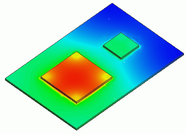
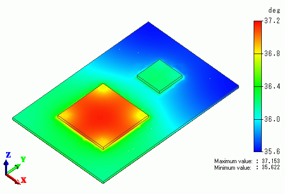
The temperature distribution is shown below.

MAINCHIP has the highest temperature in this model.
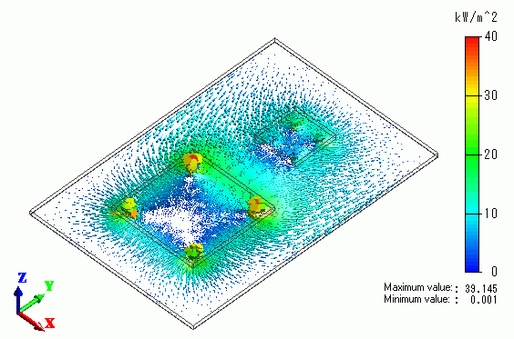
The vectors of the heat flux are shown below.

The heat is well transfered through the via holes.

