CAE Software【Femtet】Murata Software Co., Ltd.

Example19 Time-Dependent Heat Source (Transient Analysis)
General
-
Two heat sources are placed on a substrate. The heat is released to the ambient by natural convection.
The transient analysis is performed. A heat source generates heat for a certain period.
-
The model is the same as Exercise 14: Natural Convection with Correction Coefficient Automatically Calculated.
-
The temperature distribution and the heat flux vectors are solved.
-
Unless specified in the list below, the default conditions will be applied.
Analysis Space
|
Item |
Settings |
|
Analysis Space |
3D |
|
Model unit |
mm |
Analysis Conditions
|
Item |
Settings |
|
Solver |
Thermal Analysis [Watt] |
|
Analysis Type |
Transient analysis |
|
Options |
None |
The Transient Analysis tab is set up as follows. The total number of steps is 20. The time step is 60 second.
Therefore, the temperature distributions for 1200 seconds are solved.
|
Tabs |
Setting Item |
Settings |
||||||||
|
Transient analysis |
Table |
|
||||||||
|
Initial Temperature |
25[deg] |
Model
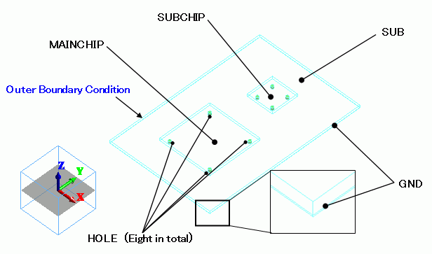
The same as Exercise 14. The material properties and the boundary conditions are the same as well.
Model
-
To use the boundary condition of “Natural convection (automatic calculation)”, the model must be oriented so that the negative Z direction points the ground.
Body Attributes and Materials
The finer mesh size is set for via holes (HOLE), where the heat flux is expected to change drastically.
|
Body Number/Type |
Body Attribute Name |
Material Name |
Mesh Size |
|
0/Solid |
SUB |
006_Glass_epoxy *1 |
|
|
1/Solid |
GND |
008_Cu *2 |
|
|
2/Solid |
MAINCHIP |
001_Alumina *2 |
|
|
3/Solid |
SUBCHIP |
001_Alumina *2 |
|
|
4/Solid |
HOLE |
008_Cu *2 |
0.5 |
|
5/Solid |
HOLE |
008_Cu *2 |
0.5 |
|
6/Solid |
HOLE |
008_Cu *2 |
0.5 |
|
7/Solid |
HOLE |
008_Cu *2 |
0.5 |
|
8/Solid |
HOLE |
008_Cu *2 |
0.5 |
|
9/Solid |
HOLE |
008_Cu *2 |
0.5 |
|
10/Solid |
HOLE |
008_Cu *2 |
0.5 |
|
11/Solid |
HOLE |
008_Cu *2 |
0.5 |
*1 Available from the Material DB.
*2 Available from the Material DB. The specific heat is manually entered.
The heat sources of MAINCHIP and SUBCHIP are set up as follows.
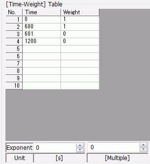
MAINCHIP is time-dependent. It generates 0.2[W] heat for 600[s]. After that, no heat is generated.
|
Body Attribute Name |
Tab |
Settings |
|
MAINCHIP |
Heat Source |
0.2[W]
Weight function
|
|
SUBCHIP |
Heat Source |
0.1[W] |
Boundary Conditions
Select “Natural convection (automatic calculation)” on the outer boundary condition.
|
Boundary Condition Name/Topology |
Tab |
Boundary Condition Type |
Settings |
|
Outer Boundary Condition |
Heat |
Heat Transfer/Ambient Radiation |
Natural convection (automatic calculation) Room temperature: 25[deg] |
* The correction coefficient for the natural convection is calculated automatically. See [Heat Transfer/Ambient Radiation] for more information.
Results
The figure below shows the heat density at 600[s] and 630[s].
MAINCHIP is not generating heat at 630[s].
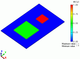
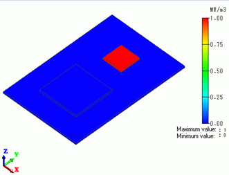
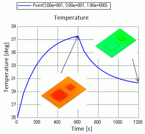
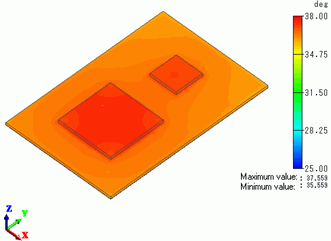
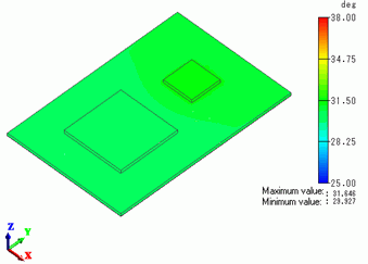
The figure below shows the heat density at 600[s] and 1200[s].
The temperature decrease from 600[s] to 1200[s].
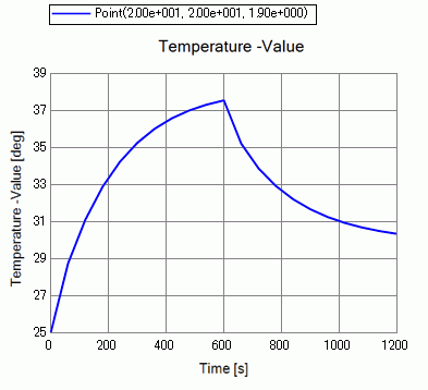
Plotted below is the temperature at the center of MAINCHIP top face, (20, 20, 1.9).
The temperature continues to go up while the heating is on. As soon as the heating is off, it starts to go down.
