CAE Software【Femtet】Murata Software Co., Ltd.

Example21 Measurement of the Thermal Resistance and the Heat Flow

General
-
Heat flow and thermal resistance are solved with a heat body and heat radiation from boundary.
-
For the second model, heat flow and thermal resistance are solved in the arbitrary domain using measuring terminal boundary condition.
Analysis Conditions
|
Item |
Settings |
|
Solver |
Thermal Analysis [Watt] |
|
Analysis Space |
3D |
|
Analysis Type |
Steady-state analysis |
|
Model unit |
mm |
|
Options |
N/A |
Graphical Objects
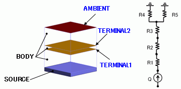
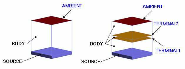
Two solid box bodies are defined. For the Model 1, body attribute of “heat source” is applied to the end of body and boundary condition of “heat transfer/ambient radiation” is applied to the other end.
For the Model 2, the solid body is cut in the middle and “measuring terminal” boundary condition is applied to the sections.
General mesh size is 1.0

Body Attributes and Materials
|
Body Number/Type |
Body Attribute Name |
Material Name |
|
0/Solid |
BODY |
MAT |
|
1/Solid |
SOURCE |
MAT_SOURCE |
The heat source of the body attribute [SOURCE] is set as follows.
|
Body Attribute Name |
Tab |
Settings |
|
SOURCE |
Heat Source |
0.0011[W] |
The thermal conductivity of the material properties [MAT], [MAT_SOURCE] are set as follows.
|
Material Name |
Tab |
Setting |
|
MAT |
Thermal Conductivity |
0.01[W] |
|
MAT_SOURCE |
Thermal Conductivity |
100[W] |
Boundary Conditions
|
Boundary Condition Name/Topology |
Tab |
Boundary Condition Type |
Settings |
|
AMBIENT/Face |
Heat |
Heat Transfer/Ambient Radiation |
Ambient Temperature: 25 [deg] Select Ambient Radiation (radiation rate) |
|
TERMINAL1/Face (for Model 2 only) |
Heat |
Measuring Terminal |
N/A |
|
TERMINAL2/Face (for Model 2 only) |
Heat |
Measuring Terminal |
N/A |
Results
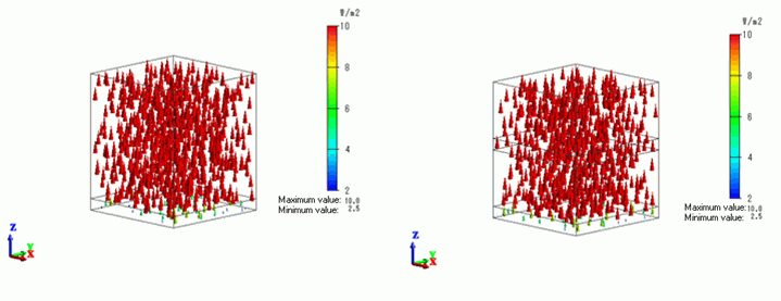
The vector diagrams of the heat flux of the Models 1 and 2 are shown below. The unit of the color scale is [W/m2].

Compared with the Model 1, the Model 2 has “Measuring terminal” added as the boundary condition. The result is not different from the Model 1.
The heat flux of 10[W/m2] is exhibited in the BODY.
The heat flow in the BODY is 0.001[W] with the section area of 100[mm]
All heat of the heat source of 0.001[W] is flowing upward.
The heat flow of the Model 1 is shown in the table below.

At Q1-2, the heat of 0.001[W] is flowing from the heat source body SOURCE (Terminal 1) is flowing toward the boundary AMBIENT (Terminal 2).
At Q1-Ambient, the heat of 0.001[W] is flowing from the boundary AMBIENT (Terminal 2) toward the ambient.
As natural convection and ambient radiation are set concurrently as boundary conditions, their details are also shown.
The heat flow of the Model 2 is shown in the table below.

At Q1-2, the heat of 0.001[W] is flowing from the heat source body SOURCE (Terminal 1) is flowing toward the measuring terminal TERMINAL1 (Terminal 2).
At Q2-3, the heat of 0.001[W] is flowing from the measuring terminal TERMINA1 (Terminal 2) is flowing toward the measuring terminal TERMINAL2 (Terminal 3).
At Q3-4, the heat of 0.001[W] is flowing from the measuring terminal TERMINAL2 (Terminal 3) is flowing toward the boundary AMBIENT (Terminal 4).
The thermal resistance of the Model 1 is shown in the table below.

At R1-2, the thermal resistance is 11000[deg/W] across the heat source body SOURCE (Terminal 1) and the boundary AMBIENT (Terminal 2).
With thermal conductivity: 0.01 [W/m/deg], thickness: 11 [mm], and section: 100 [mm],
the theoretical value is 11 x 1e-3 / ( 0.01 * 100 x 1e-6 ) = 11000 [deg/W].
The results and the theoretical value match.
At R2-Ambient, the thermal resistance is 1102[deg/W] across the boundary AMBIENT (Terminal 2) and the ambient.
As natural convection and ambient radiation are set concurrently as boundary conditions, their details are also shown.
The thermal resistance of the Model 2 is shown in the table below.

The thermal resistance across the heat source body SOURCE (Terminal 1) and the boundary AMBIENT (Terminal 2) of the Model 1 is
divided at the measuring terminals and details of the thermal resistance are shown.
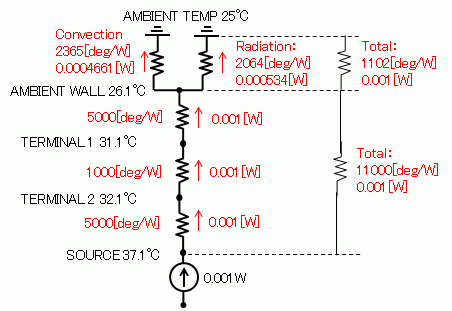
At R1-2, the thermal resistance is 5000[deg/W] across the heat source body SOURCE (Terminal 1) and the measuring terminal TERMINAL1 (Terminal 2).
At R2-3, the thermal resistance is 1000[deg/W] across the measuring terminal TERMINAL1 (Terminal 2) and the measuring terminal TERMINAL2 (Terminal 3).
At R3-4, the thermal resistance is 5000[deg/W] across the measuring terminal TERMINAL2 (Terminal 3) and the boundary AMBIENT (Terminal 4).
The results are reasonable considering each thickness is 5[mm], 1[mm], and 5[mm].
The equivalent circuit of the results is shown as follows.


