
CAE Software【Femtet】Murata Software Co., Ltd.

Example6 Temperature Dependency of Young’s Modulus
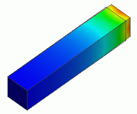
General
-
The model’s material has a temperature-dependent Young’s modulus.
It deforms when it is subjected to thermal load.
-
The deformation, the displacement and the mechanical stress are solved.
-
Unless specified in the list below, the default conditions will be applied.
Analysis Space
|
Item |
Settings |
|
Analysis Space |
3D |
|
Model unit |
mm |
Analysis Conditions
Select Thermal analysis and Mechanical stress analysis.
|
Item |
Settings |
|
Solvers |
Thermal analysis [Watt] |
|
Thermal-Analysis Type |
Steady-state analysis |
|
Options |
N/A * |
* “Thermal Load” is selected by default for the thermal load-mechanical stress coupled analysis.
The Step/Thermal Load tab is set as follows.
|
Tab |
Setting Item |
Setting |
|
Step/Thermal Load * |
Reference temperature |
0[deg] |
* The reached temperatures come from the thermal analysis.
Model
A rectangular rod is defined. The material is set with temperature-dependent coefficient of expansion.
The rod’s end faces are set with different temperature and displacement by “temperature” and “displacement boundary conditions.
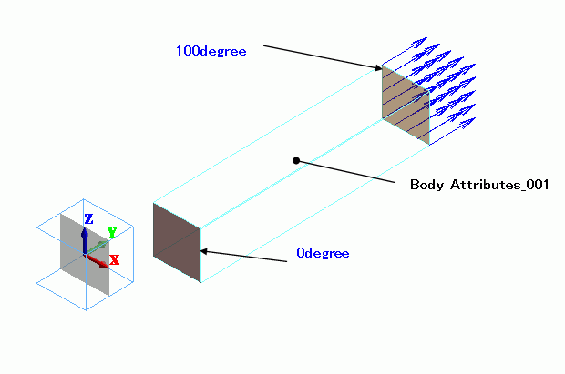
Body Attributes and Materials
|
Body Number/Type |
Body Attribute Name |
Material Name |
|
0/Solid |
Body_Attribute_001 |
Material_Property_001 |
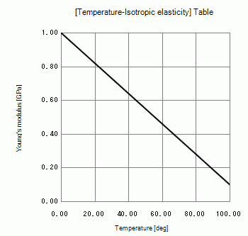
Temperature dependency of Young’s modulus is set on the nonlinearity table.
|
Material Name |
Tab |
Settings |
|||||||||
|
ElasticMaterial |
Elasticity |
Material Type: Elastic/Isotropic
Temperature Dependency: Yes [Temperature-Isotropic elasticity] Table *
* This is not the actual material’s property. |
|||||||||
|
Thermal Conductivity |
1[W/m/deg] |
Press the Graph button. The following graph will appear.
Boundary Conditions
Thermal analysis is performed based on the boundary conditions below. The resulting temperature distribution is forwarded to mechanical stress analysis.
|
Boundary Condition Name/Topology |
Tab |
Boundary Condition Type |
Settings |
|
100degree/Face |
Thermal |
Temperature |
100[deg] |
|
Mechanical |
Displacement |
Select UY UY=0[m] |
|
|
0degree/Face |
Thermal |
Temperature |
0[deg] |
|
Mechanical |
Displacement |
Select UY UY=0.1×10^-3[m] |
Results
The temperature distribution as a result of Watt is shown below.
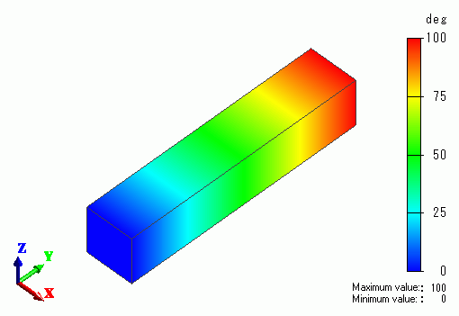
The vectors of the strain are shown below.
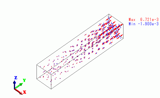
The strain is greater towards the rod’s right end.
The vectors of the mechanical stress are shown below.
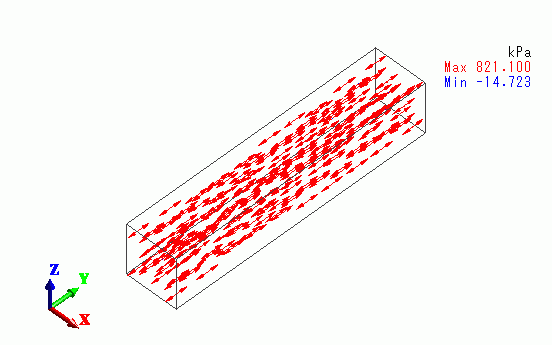
The tensile stress is exhibited in the y direction.

