Set the boundary conditions.
Forced inflow (flow velocity) and natural outflow are set to inlet and outlet respectively.
The boundary conditions are distinguished by name. It is not allowed to assign the same name to the different boundary conditions
At the inflow port, the molar concentration of the diffusing material flowing therein is specified.
-
On the [Model] tab, go to
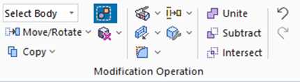 , ,
and select [Select Face] on the drop-down list at  . .
-
How to Switch the Object to Select
-
Concept of Body and Topology
|
|
-
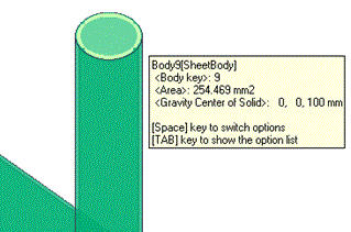
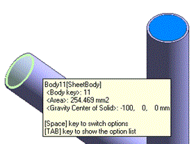
Highlight the face of the sheet body at the upper opening of the vertically oriented pipe, and click to select.
|
|
-
On the [Attribute] context tab
 , ,
click [Boundary Condition]  . .
|
|
-
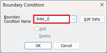
In the [Boundary Condition] dialog box, enter
Boundary Condition Name: Inlet_1
and click  . .
-
Any name is acceptable.
|
|
-
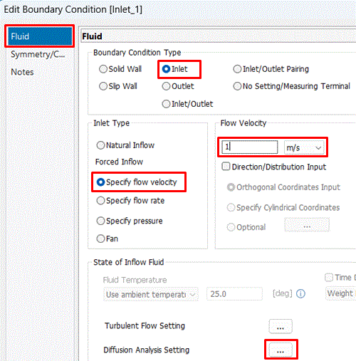
In the [Edit Boundary Condition] dialog box, apply settings so that the flow velocity becomes 1[m/s].
On the [Fluid] tab,
select [Boundary Condition Type]: Inlet,
confirm that Inlet Type: Specify flow velocity is selected,
enter 1 [m/s] and click the button for diffusion analysis setting.
|
|
-
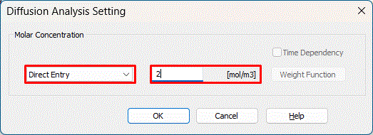
In the diffusion analysis setting dialog box,
select [Direct Entry] to enter a molar concentration of 2 [mol/m3],
and click  . .
Then, click in the [Edit Boundary Condition] dialog box,
furthermore click to exit the [Boundary Condition] dialog box.
|
 |
-
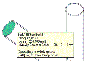
Highlight the face of the sheet body at the left opening of the horizontally oriented pipe, and click to select.
|
|
-
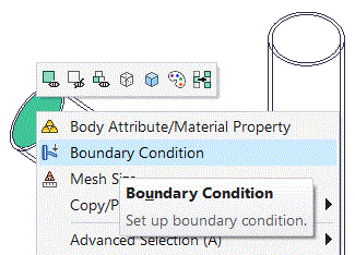
Right-click to open the menu, and click [Boundary Condition].
|
|
-
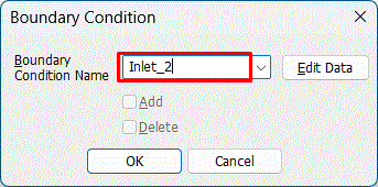
In the [Boundary Condition] dialog box, enter
Boundary Condition Name: Inlet_2
and click .
-
Any name is acceptable.
|
|
-
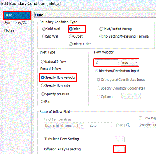
In the [Edit Boundary Condition] dialog box,
on the [Fluid] tab,
select [Boundary Condition Type]: Inlet,
confirm that Inlet Type: Specify flow velocity is selected,
enter 2 [m/s],
and click the button for diffusion analysis setting.
|
|
-
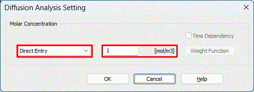
In the diffusion analysis setting dialog box,
select [Direct Entry] to enter a molar concentration of 1 [mol/m3],
and click .
Then, click in the [Edit Boundary Condition] dialog box,
furthermore click to exit the [Boundary Condition] dialog box.
|
 |
-
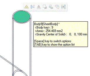
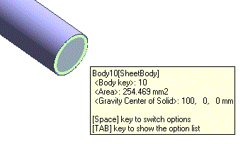
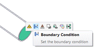
Highlight the face of the sheet body at the right opening of the horizontally oriented pipe, and click to select. In the mini toolbar that appears, select [Boundary Condition] .
|
|
-
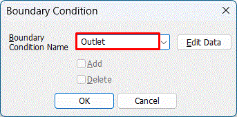
In the [Boundary Condition] dialog box, enter
[Boundary Condition Name]: Outlet
and click .
-
Any name is acceptable.
|
|
-
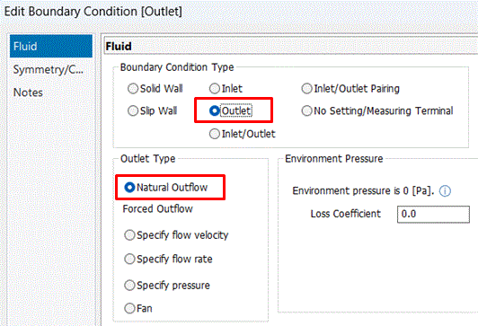
In the [Edit Boundary Condition] dialog box,
on the [Fluid] tab,
select [Boundary Condition Type]: Outlet,
confirm that Outlet Type: Natural Outflow is selected,
and click .
Then click to exit the [Boundary Condition] dialog box.
|
|
|
The boundary conditions have been set.
|
|



 Prev Next