CAE Software【Femtet】Murata Software Co., Ltd.

Example17 Floating Capacitance

General
-
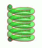
The floating capacitance of a helical coil is analyzed.
-
Unless specified below, default setting is applied.
Analysis Space
|
Item |
Setting |
|
Analysis Space |
3D |
|
Model unit |
mm |
Analysis Conditions
|
Item |
Setting |
|
Solver |
Electric field analysis |
|
Analysis Type |
Static analysis |
|
Material |
Dielectric |
|
Options |
None |
Set the Mesh Tab as follows.
|
Tab |
Setting Item |
Setting |
|
Mesh |
Meshing Setup |
Deselect [Automatically set the general size] General mesh size: 2 [mm] |
Graphical Objects
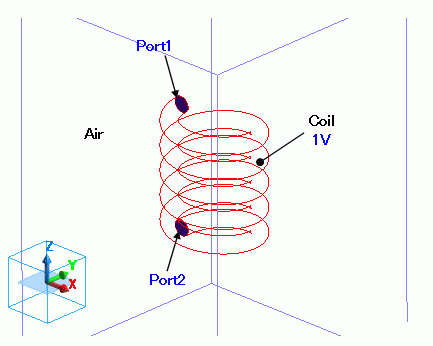
A Helical coil is a solid body.
1V of electric wall is set on the entire body.
Port is set to the node where the floating capacitance is calculated.

Body Attributes and Materials
|
Body Number/Type |
Body Attribute Name |
Material Name |
|
0/Solid |
Coil |
Coil |
|
1/Solid |
Air |
* 000_Air |
* Available from the Material DB
Perfect conductor is set to the coil.
|
Material Name |
Tab |
Setting |
|
Coil |
Conductivity |
Conductivity Type: Perfect conductor |
Boundary Condition
Set the electric wall of 1V on the whole of the coil body.
I/O ports are set on the nodes where the floating capacitance is obtained.
|
Boundary Condition Name/Topology |
Tab |
Boundary Condition Type |
Setting |
|
1V/Face |
Electric |
Electric wall |
Voltage specified, 1[V] |
|
Port1/Face |
Electric |
I/O Port |
|
|
Port2/Face |
Electric |
I/O Port |
|
|
Outer Boundary Condition |
Electric |
Magnetic wall |
|
Results
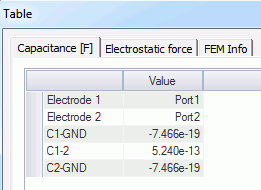
To see the calculation results, go to the [Results] tab

and click [Table] ![]() .
.

C1-2 is the floating capacitance. It is about 0.5 [pF].

