
CAE Software【Femtet】Murata Software Co., Ltd.
Example6 Patch Antenna
General
-
The characteristics of a patch antenna are analyzed.
-
The S-parameters at the feeding port are solved.
-
Unless specified in the list below, the default conditions will be applied.
-
The output of field data is switched off.
-
That reduces the size of results file.
-
[How to Reduce the Calculation Time]
Analysis Space
|
Item |
Settings |
|
Analysis Space |
3D |
|
Model unit |
mm |
Analysis Conditions
|
Item |
Settings |
|
Solvers |
Electromagnetic Analysis [Hertz] |
|
Analysis Type |
Harmonic analysis |
|
Options |
Select “Ignore the influence of face/edge electrode thickness” * Field Data to Save: Don’t save ** |
* This is the default setting.
The thickness of patch antenna electrode is ignored, which is effectively the same as the conductive wall boundary condition set on sheet body
** In this session, we are interested in S-parameters only.
Therefore the output of field data is opted out.
That reduces the size of result file.
Mesh tab, Harmonic analysis tab and Open boundary tab are set as follows.
|
Tab |
Setting Item |
Settings |
|
Mesh Tab |
Element type |
2nd-order element |
|
Multigrid/Adaptive Mesh Method |
Select [Use the adaptive mesh method]. |
|
|
Frequency-Dependent Meshing |
Reference frequency: 10×10^9[Hz] Select “The conductor bodies thicker than the skin depth constitute the boundary condition.”
There are no conductive solid bodies in this analysis model. Therefore the setting above is irrelevant. |
|
|
Harmonic analysis |
Frequency |
Minimum: 1×10^9[Hz] Maximum: 10×10^9[Hz] |
|
Sweep Type |
Select Linear step Division number: 200 |
|
|
Sweep Setting |
Select Fast sweep S-parameters variation: 1×10^-3 |
|
|
Input |
1.0[W] |
|
|
Open boundary |
Type |
Absorbing boundary |
|
Order of Absorbing Boundary |
1st degree |
Model
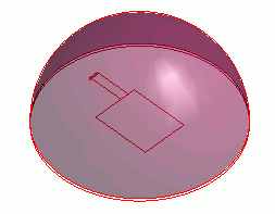
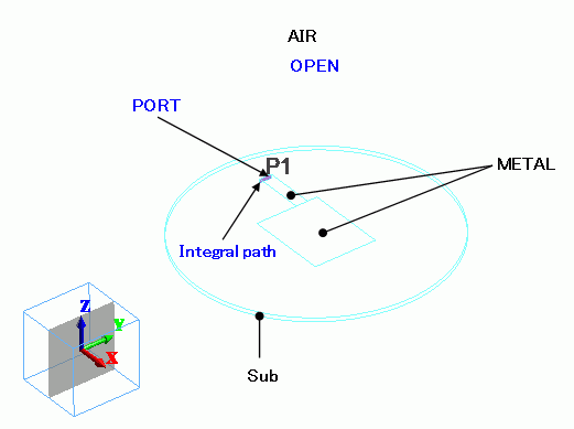
Antenna pattern (Metal) is created on a circular substrate (sub).
It is covered with the hemispherical air (AIR). The open boundary (OPEN) is set on the hemisphere.
An imprinting body is defined at the feeding point, where the I/O port boundary condition is set. The bottom face of the substrate (sub) is set with the boundary condition of Electric wall.
Body Attributes and Materials
You may give the thickness to METAL in the body attribute. That does not affect the simulation.
(Related information: Analysis Condition, Electromagnetic Analysis tab, and “Ignore the influence of face/edge electrode thickness”)
|
Body Number/Type |
Body Attribute Name |
Material Name |
|
0/Solid |
AIR |
000_Air(*) |
|
1/Sheet |
METAL |
003_Ag * |
|
2/Solid |
sub |
006_Glass_epoxy * |
|
3/Sheet |
METAL |
003_Ag * |
|
4/Sheet |
Imprinting body |
|
* Available from the Material DB
Boundary Conditions
The bottom face of the substrate (sub) is set with the boundary condition of “Electric wall”.
|
Boundary Condition Name/Topology |
Tab |
Boundary Condition Type |
Settings |
|
PORT/Face |
Electric |
I/O Port |
Reference Impedance: Select “Specify” and enter 50[Ohm]. Number of Modes Number of precalculated modes: 5 Number of modes used in the actual analysis: 1 Select modes: none |
|
OPEN/Face |
Electric |
Open boundary |
|
|
Outer Boundary Condition |
Electric |
Electric wall |
|
Results
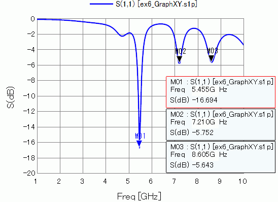
S-parameter S11 at the feeding point is shown below.
It is matched at 5.4GHz.
-
-
See [Exercise 7: Dipole Antenna].
-
See also [Electromagnetic Waves Directivity].
-