CAE Software【Femtet】Murata Software Co., Ltd.
Example22 S-Parameter Analysis of Balanced Line
General
-
The characteristics of a balanced line are analyzed.
-
S-parameters are solved for the differential mode or common mode.
-
Unless specified in the list below, the default conditions will be applied.
Analysis Space
|
Item |
Settings |
|
Analysis Space |
3D |
|
Model unit |
mm |
Analysis Conditions
|
Item |
Settings |
|
Solvers |
Electromagnetic Analysis [Hertz] |
|
Analysis Type |
Harmonic analysis |
|
Options |
Select “Ignore the influence of face/edge electrode thickness” * |
* This is the default setting. There are no face electrodes with this model. Therefore it is irrelevant to select it or not.
xx
Mesh tab, Harmonic analysis tab and Open boundary tab are set as follows.
|
Tab |
Setting Item |
Settings |
|
Mesh Tab |
Frequency-Dependent Meshing |
Reference frequency: 1×10^9[Hz] Select “The conductor bodies thicker than the skin depth constitute the boundary condition.” |
|
Harmonic analysis |
Frequency |
Minimum: 0.1×10^9[Hz] Maximum: 5×10^9[Hz] |
|
Sweep Type |
Select Linear step Division number: 10 |
|
|
Sweep Setting |
Select Discrete sweep |
|
|
Input |
1.0[W] |
|
|
Open boundary |
Type |
Absorbing boundary |
|
Order of Absorbing Boundary |
1st degree |
* Fast sweep is avoided for higher accuracy. The number of frequencies is relatively low, so the calculation will not take long.
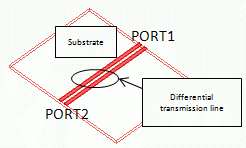
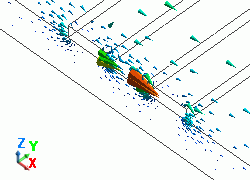
Model
Two electrodes are created on a substrate. They function as a balanced line.
They are covered with rectangle air space.
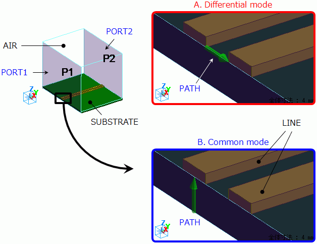
Air and ports at both ends of the substrate are set as in the diagram below.
Location of the integral path is different between the differential mode analysis and common mode analysis.
For the differential mode analysis, the integral path is set between two electrodes.
For the common mode analysis, it is set between one of the electrodes and the bottom of the substrate.
The bottom of the substrate contacts the electric wall outer boundary condition.
Body Attributes and Materials
|
Body Number/Type |
Body Attribute Name |
Material Name |
|
0/Solid |
SUBSTRATE |
006_Glass_epoxy * |
|
1/Solid |
AIR |
000_Air(*) |
|
2/Solid |
LINE |
003_Ag * |
|
3/Solid |
LINE |
003_Ag * |
|
5/Sheet |
Imprinting body |
|
|
6/Sheet |
Imprinting body |
|
* Available from the Material DB
Boundary Conditions
Boundary condition settings are different between the differential mode analysis and the common mode analysis.
The different settings are shown in red as follows.
|
Boundary Condition Name/Topology |
Tab |
Boundary Condition Type |
Setting for Differential Mode Analysis |
Setting for Common Mode Analysis |
|
PORT1/Face |
Electric |
I/O Port |
Integral path: set “PATH” as in the diagram A above Reference Impedance:
Number of Modes:
|
Integral path: set “PATH” as in the diagram B above Reference Impedance:
Number of Modes:
|
|
PORT2/Face |
Electric |
I/O Port |
Same as above. |
Same as above. |
|
Outer Boundary Condition |
Electric |
Electric wall |
|
|
Results
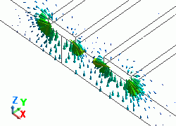
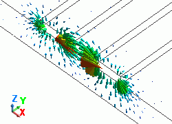
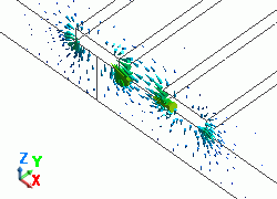
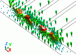
Propagation Mode
Select Port for [Analysis type]. From [Mode], select 5GHz which is the maximum analysis frequency.
As the number of modes to precalculate is set to 5,
five propagation modes are calculated for one frequency.
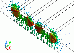
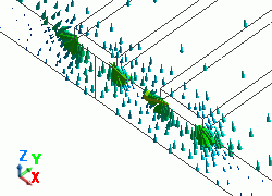
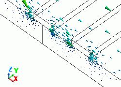
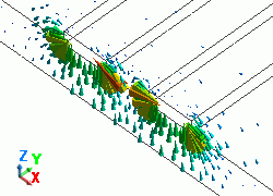
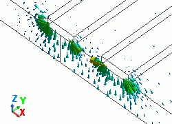
The diagram below shows the electric fields of five propagation modes calculated at PORT1 with 5GHz.
A part of the Propagation constant dialog box is also shown at the bottom of each diagram below.
Propagation constant dialog box can be opened from Mode Information of the [Chart] button.
|
Mode |
Differential Mode Analysis |
Common Mode Analysis |
||||
|
50: 5.000000e+09Hz: (0) |
|
|
||||
|
51: 5.000000e+09Hz: (1) |
|
|
||||
|
52: 5.000000e+09Hz: (2) |
|
|
||||
|
53: 5.000000e+09Hz: (3) |
|
|
||||
|
54: 5.000000e+09Hz: (4) |
|
|
In both differential mode analysis and common mode analysis,
common mode is calculated first, and then differential mode is calculated at PORT1.
As only mode01 is selected for the I/O port setting for the differential mode analysis,
you can see that only second mode (differential mode) is used in the 3D analysis.
In the common mode analysis, as mode selection is not done,
only first mode (common mode) is used in the 3D analysis.
At PORT2 too, differential mode is used in the 3D analysis for the differential mode analysis,
and the common mode is used in the 3D analysis for the common mode analysis.
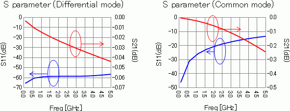
S-parameters
The diagrams below show the S-parameters of the differential mode and common mode analyses.
S-parameters of the differential mode analysis are shown in the left diagram and the common mode analysis in the right diagram.
Blue curves represent reflection characteristics S11 and red curves represent transmission characteristics S21.