
CAE Software【Femtet】Murata Software Co., Ltd.
Example27 TDR Analysis
General
-
S-parameters obtained in the electromagnetic waves harmonic analysis
are converted to a time series of impedance by TDR in Descartes.
-
Unless specified in the list below, the default conditions will be applied.
-
Obtain this session’s project file. (Save the project file before open)
Analysis Space
|
Item |
Setting |
|
Analysis Space |
3D |
|
Model unit |
mm |
Analysis Condition
|
Item |
Setting |
|
Solver |
Electromagnetic waves analysis [Hertz] |
|
Analysis Type |
Harmonic analysis |
|
Tab |
Setting Item |
Setting |
|
Mesh |
Adaptive Mesh Setting |
General
|
|
Frequency-Dependent Meshing |
Reference frequency: 30×10^9[Hz] Select “The conductor bodies thicker than the skin depth constitute the boundary condition.” |
|
|
Harmonic Analysis |
TDR Analysis Setting |
|
|
Frequency (*2) |
|
|
|
Frequency Sweep |
Discrete sweep (*3) |
*1 The number of iterations is changed to 20 as the adaptive meshing does not converge with the default setting of 5. Set the smaller number if you want to shorten the calculation time.
*2 Frequency is automatically set based on the TDR analysis setting.
*3 Since the analysis frequency is wide (793MHz to 50GHz), discrete sweep is opted so as to avoid worsening analysis accuracy.
*3 To shorten a calculation time, use fast sweep or parallel discrete sweep.
Model
A is a stripline (LINE) is formed inside a substrate (SUBSTRATE).
The stripline has a discontinuous part , and the electromagnetic wave reflects because the characteristic impedance changes here.

Body Attributes and Materials
|
Body Number/Type |
Body Attribute Name |
Material Name |
|
4/Sheet |
LINE |
PEC |
|
6/Solid |
SUBSTRATE |
DIELECTRIC |
|
Material Name |
Permittivity |
Conductivity |
|
DIELECTRIC |
Relative permittivity: 3.9 |
Conductivity type: Insulator |
|
PEC |
(Default value) |
Conductivity type: Perfect conductor |
Boundary Condition
|
Boundary Condition Name/Topology |
Tab |
Boundary Condition Type |
Setting |
|
PORT1/Face |
Electric |
Port |
Integral Path:
Reference impedance: select
|
|
PORT2/Face |
Electric |
Port |
Same as above. |
|
Outer Boundary Condition |
Electric |
Electric wall |
|
-
In order to convert the S-parameters to the time series of impedance of TDR in Descartes,
reference impedance of all ports must be the same real number.
Results

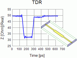
Fig 1: TDR analysis results (impedance graph) and a relationship between time and substrate’s position
Fig 1 shows the time series of impedance of TDR as a result of analysis.
Fig 1 also shows the relationship between the time and the substrate’s position.
The relationship between the time and the substrate’s position is obtained as follows.
The speed of electromagnetic waves that advance the stripline v [m/s] can be represented, by using speed of light c0 [m/s] and substrate’s relative permittivity εr,
as v = c0 / √εr
Based on the speed of light: c0 = 299792458 [m/s] and the substrate’s relative permittivity: εr = 3.9,
the speed of electromagnetic waves is about 1.518 × 10⁸ m/s.
With TDR, impedance of the line is calculated by observing the reflecting wave.
The electromagnetic waves entered from port 1 (PORT1) are reflected in the first discontinuous part at the distance of 10 mm from the port 1.
The reflecting waves will travel the distance of 20mm by the time the they return to the port 1.
It takes about 131.7ps for the electromagnetic waves with a speed of 1.518 × 10⁸ m/s to travel the distance of 20 mm.
On the TDR graph, you can notice that the impedance changes greatly at around the time of 131.7ps.
The electromagnetic waves that passed the first discontinuous part are partially reflected in the discontinuous part 20 mm away from the port 1.
The electromagnetic waves reflected here will travel the distance of 40mm by the time they return to the port 1.
It takes about 263.5ps for the electromagnetic waves with a speed of 1.518 × 10⁸ m/s to travel the distance of 40 mm.
On the TDR graph, you can notice that the impedance changes greatly at around the time of 263.5ps.
The electromagnetic waves that passed the second discontinuous part eventually reach the port 2 (PORT2).
Since the reference impedance of 50Ω is set on the port 2, if the characteristic impedance of the stripline is not 50Ω,
the electromagnetic waves are partially reflected also at the port 2.
The electromagnetic waves reflected at the port 2 will travel the distance of 60 mm by the time they return to the port 1.
It takes about 395.2ps for the electromagnetic waves with a speed of 1.518 × 10⁸ m/s to travel the distance of 60 mm.
On the TDR graph, you can notice that the impedance changes greatly at around the time of 395.2ps.
The result confirms that it is constantly 50Ω after 395.2ps.
-
In the TDR analysis setting, time is set at 400 ps to determine the analysis frequency for the harmonic analysis.
The graph, however, shows the result up to 630 ps.
It is because Femtet adjusts the number of data when determining the analysis frequency.
Descartes applies Fourier transform to convert S matrix to impedance of TDR.
The number of data that can be handled by the Fourier transform is 2n (n is a positive integer).
To divide the rise time of 30ps into three steps, the time step width is set to 10ps.The number of data obtained from the results over the time of 400ps with 10ps-time step width will be 41.
As 41 data are not supported by the Fourier transform, the analysis frequency is set up so that 64(= 26) data are prepared.
Since there are 64 data with time step width of 10ps, the results over the time of 630ps will be obtained.See also [TDR Analysis Setting].