CAE Software【Femtet】Murata Software Co., Ltd.

Example1 Microwave Oven

General
-
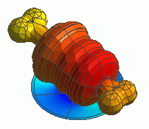
The heating of a piece of meat on the bone placed in a microwave oven is simulated.
-
It is solved by cascading the electromagnetic waves analysis and the thermal analysis.
-
Unless specified in the list below, the default conditions will be applied.
Analysis Space
|
Item |
Settings |
|
Analysis Space |
3D |
|
Model unit |
mm |
Analysis Conditions
|
Item |
Settings |
|
Solver |
Electromagnetic Analysis [Hertz] Thermal Analysis [Watt] |
|
Analysis Type |
Electromagnetic waves analysis: Harmonics analysis Thermal analysis: Steady-state analysis |
|
Options |
Select “Ignore the influence of face/edge electrode thickness” * |
* This is the default setting. There are no face electrodes with this model. Therefore it is irrelevant to select it or not.
xx
Mesh tab, Harmonic analysis tab and Open boundary tab are set as follows.
|
Tabs |
Setting Item |
Settings |
|
Mesh |
Mesh Size |
20 |
|
Element type |
2nd-order element |
|
|
Adaptive mesh |
Off (to shorten the calculation time) |
|
|
Frequency-Dependent Meshing |
Reference frequency: 2.45×10^9[Hz] |
|
|
Harmonic analysis |
Frequency |
Minimum: 2.45×10^9[Hz] Maximum: 2.45×10^9[Hz] |
|
Input |
10[W] * |
* The power of actual microwave ovens is much higher than this.
The temperature distribution at steady state is analyzed in this exercise. Therefore, if the actual power is applied, the resulting temperature will be too high.
The input power is low to prevent it.
Model
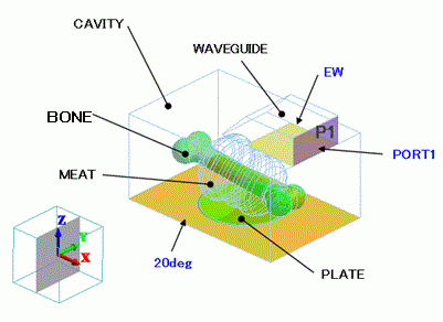
A waveguide is placed on the top of a cavity box. An I/O port is set at the end of the waveguide.
The meat on the bone is placed on a plate. The temperature of the bottom face of CAVITY is 20[deg].

Body Attributes and Materials
|
Body Number/Type |
Body Attribute Name |
Material Name |
Mesh Size |
|
0/Solid |
CAVITY |
000_Air(*) |
|
|
5/Solid |
WAVEGUIDE |
000_Air(*) |
|
|
6/Sheet |
Imprinting body |
|
|
|
13/Solid |
PLATE |
PLATE |
8 |
|
75/Solid |
BONE |
BONE |
8 |
|
96/Solid |
MEAT |
WATER |
|
* Available from the Material DB
|
Material Name |
Tab |
Properties |
|
PLATE |
Permittivity |
Relative Permittivity: 7.0 tanD: 0.0 |
|
Thermal Conductivity |
1.5[W/m/deg] |
|
|
BONE |
Permittivity |
Relative permittivity: 7.0 tanD: 0.1 |
|
Thermal Conductivity |
1.5[W/m/deg] |
|
|
WATER |
Permittivity |
Relative Permittivity: 76.7 tanD: 0.16 |
|
Thermal Conductivity |
1.5[W/m/deg] |
Boundary Conditions
|
Boundary Condition Name/Topology |
Tab |
Boundary Condition Type |
Settings |
|
PORT1/Face |
Electric |
I/O Port |
Reference Impedance: |
|
EW/Face |
Electric |
Electric wall |
|
|
20deg/Face |
Electric |
Electric wall |
|
|
Thermal |
Temperature |
20[deg] |
|
|
Outer Boundary Condition |
Electric |
Electric wall |
|
The default settings are “Magnetic wall” and “Adiabatic” for the electric and thermal boundary conditions respectively.
Results
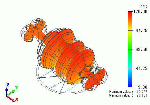
The model is well heated overall.


