Home / Tutorial / Electromagnetic Analysis (3D Harmonic Analysis) (Hertz) / 08.Set up the Ports
08.Set up the Ports
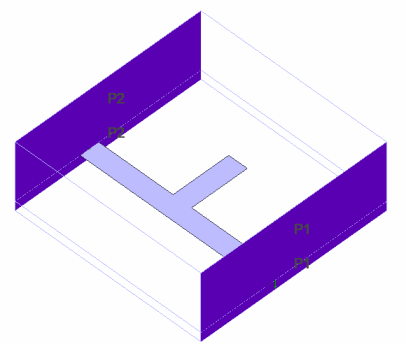
We set the port boundary conditions.
The ports on Hertz are set on the area where the transmission line exists.
Transmission line is the structure to carry electromagnetic waves. Parallel plates, microstrip lines and waveguides are the transmission lines.
The integral paths and the electric field directions are also set up here.
Procedure
-
On the [Model] tab, go to
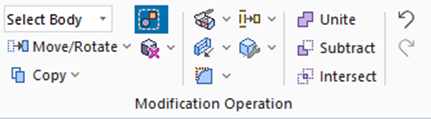 , ,
and click Select Face on the drop-down list at  . .
-
How to Switch the Object to Select
-
Concept of Body and Topology
|
|
-
Set up Port_001 first.
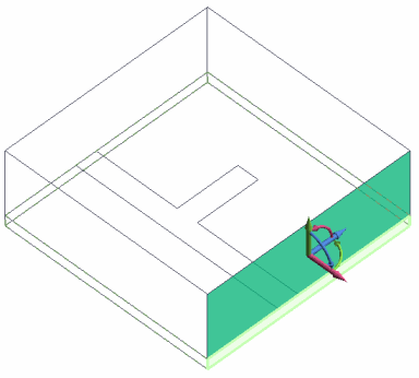
Highlight the face of the air domain for Port_001 and click to select.
|
|
-
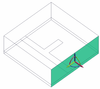
Also highlight the face of the substrate for Port_001 while pressing the <Ctrl> key and click to select.
|
|
|

Ctrl+click |
|
|
Highlight |
|
Selected |
|
-
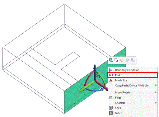
On the right-click menu, click [Port].
|
|
-
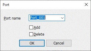
In the [Port] dialog box, the following will appear automatically
Port name: Port_001
Just click  . .
|
|
-
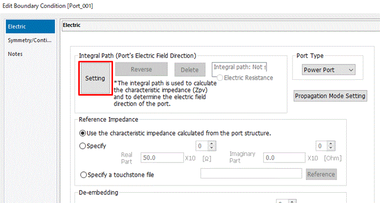
In the [Edit Boundary Condition [Port_001]] dialog box,
click  . .
|
|
-
Set up the integral paths and the electric field directions on the ports.
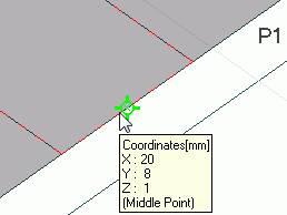
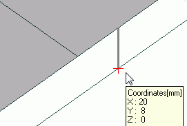
Click the startpoint on the modeling window.
The startpoint is the middle point of the edge as in the right figure.
-
To zoom in, on the [Model] tab, go to
 , ,
and click [Zoom]  , or [Zoom in to Area] , or [Zoom in to Area]  . .
-
To snap the middle point of an edge, go to the [Snap] context tab,

and enable [Middle Point]  . Other snap commands may be disabled. . Other snap commands may be disabled.
Snap is explained here
-
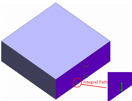
The integral path is used to calculate the characteristic impedance of the port.
See [How to Set Ports in Electromagnetic Analysis] for details.
|
|
-
Click the endpoint on the modeling window.
The endpoint is shown in the right figure.
|
|
-
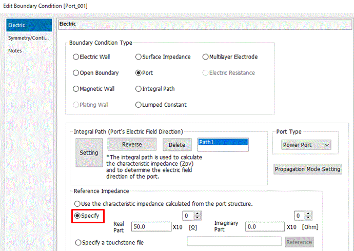
In the [Edit Boundary Condition [Port_001]] dialog box,
select [Specify] at [Reference Impedance] and click .
The integral path of Port_001 is created.
|
|
-
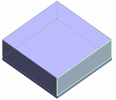
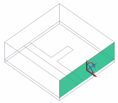
Set up Port_002.
Port_002 can be set up on the other side of the model in the same way as Port_001.
|
* Shown by wireframe. |


 .
. Prev Next