Home / Tutorial / Magnetic Analysis (Luvens, Transient Analysis of Motor) / 04.Create the Stator Core
04.Create a Stator Core
Stator core is created here.
Procedure
-
For easy operation, hide the rotor.
On the [Model] tab, go to
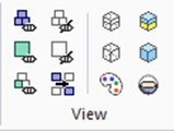
and click [Hide All]  . .
|
|
|
-
Create lines of the stator core.
On the [Model] tab, go to 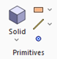 and click [Wire Body] - [Line (wire body)] and click [Wire Body] - [Line (wire body)]  . .
|
|
|
-
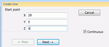
In the parameter input dialog box, enter Startpoint (X: 28, Y: 0, Z: 0) and click  . .
|
|
-
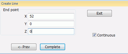
Enter Endpoint (X: 52, Y: 0, Z: 0), and click  . .
|
|
-
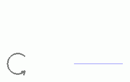
A line has been created.
Click  in the parameter input dialog box and exit. in the parameter input dialog box and exit.
|
|
-
Modify the line to form the stator core.
On the [Model] tab, go to
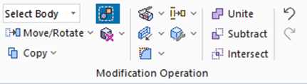
and press ▼ at the side of
[Extrude].
Then click [Revolve] on the submenu. on the submenu.
(Alternatively, right-click the mouse. On the appearing menu, select [Deform]-[Revolve])
|
|
-
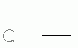
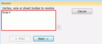
Select the Line body.
|
|
-
Click in the [Revolve] dialog box.
|
|
-
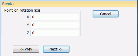
Specify the point on the rotation axis.
In the parameter input dialog box, enter Point on Rotation Axis (X: 0, Y: 0, Z: 0) and click .
|
|
-
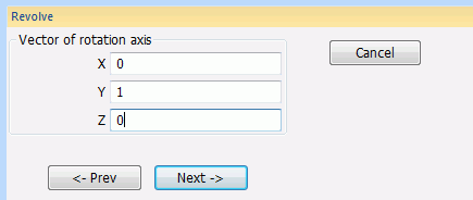
Specify the direction vector of the rotation axis
Enter Direction Vector of Rotation Axis (X: 0, Y: 1, Z: 0) and click .
|
|
-
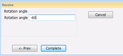
Specify the rotation angle.
Enter Rotation Angle: -60 and click
|
|
|
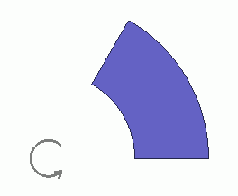
One third of the stator core has been created.
|
|


 Prev Next