Home / Tutorial / Magnetic Analysis (Luvens, Transient Analysis of Motor) / 02.Create the Rotor Core
02.Create a Rotor Core
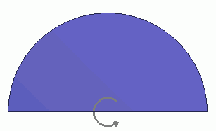
Rotor core is created here.
Procedure
-
Create circle for the rotor core.
On the [Model] tab, go to  and click ▼ at the side of [Sheet Body] and click ▼ at the side of [Sheet Body]  . .
Click []  on the submenu. on the submenu.
|
|
|
-
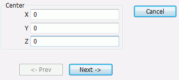
Designate the center., enter Center (X: 0, Y: 0, Z: 0) and click  . .
-
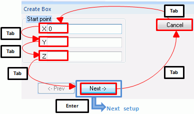
Tips on the parameter input dialog box
If the input value is nil, you don't need to enter 0 in the entry field. The blank is acceptable.
Press the <Tab> key to hop around the items in the dialog box.
Press the <Enter> key on to proceed to the next setting.
|
|
|
-
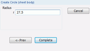
Set the radius.
Enter Radius: 27.5 and click  . .
|
|
-
Click  in the parameter input dialog box and exit. in the parameter input dialog box and exit.
-
You can also exit by pressing the <Esc> key.
|
|
|
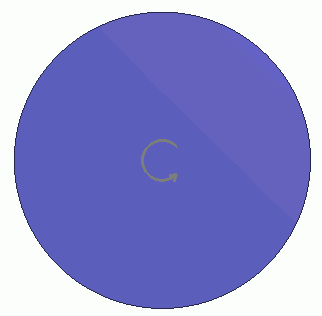
The circle has been created.
|
|
-
Cut the lower part of the body.
On the [Model] tab, go to
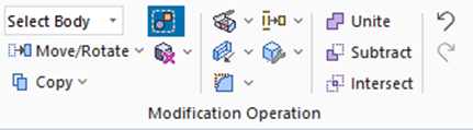
and click [Cut] . .
(Alternatively, right-click the mouse. On the appearing menu, select [Deform]-[Cut])
|
|
-
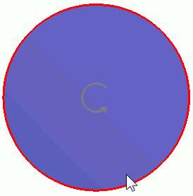
Highlight the circle and click to select it on the .
Click in the parameter input dialog box.
|
|
-
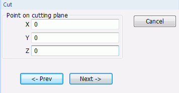
In the parameter input dialog box, enter Point on Cutting Plane (X: 0, Y: 0, Z: 0) and click .
|
|
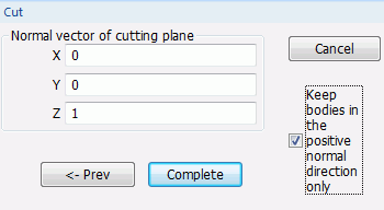
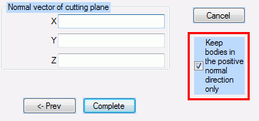
- Enter Normal Vector of Cutting Plane (X: 0, Y: 0, Z: 1),
select [Keep bodies in the positive normal direction only] and click .
|
|
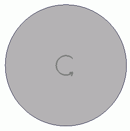
- The rotor core has been created.
Click in the parameter input dialog box and exit.
|
|
-
You can undo or redo the operation. The operations can be changed as follows;
On the [Model] tab, go to
and click [Undo] to undo the modeling or attribute operation. to undo the modeling or attribute operation.
and click [Redo]  to redo the modeling or attribute operation. to redo the modeling or attribute operation.
|
|



 .
.

 Prev Next