Home / Tutorial / Magnetic Analysis (Luvens, Transient Analysis of Motor) / 07.Set the Analysis Conditions
07.Set the Analysis Conditions
We set the analysis conditions.
Procedure
-
On the [Model] tab, go to
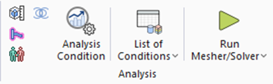 , ,
and click [Analysis Condition]  . .
The [Analysis Condition Setting] dialog will show up.
|
|
-
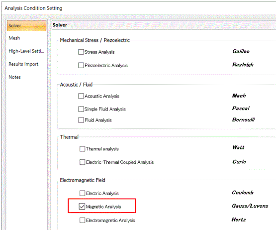
Select [Magnetic analysis 'Gauss/Luvens'] on the [Solver] tab.
|
|
-
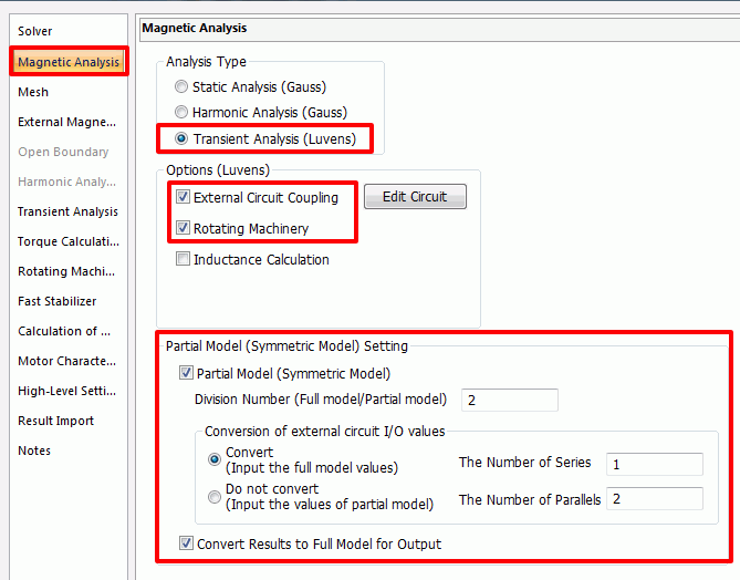
Click [Magnetic Analysis] tab and set as follows;
Select [Analysis Type]: [Transient Analysis]
[Options]: [External Circuit Coupling], select [Rotating Machinery]
[Partial Model (Symmetric Model) Setting]:
Select [Partial Model (Symmetric Model)]
Enter [Number of Divisions]: 2.
Select [Convert].
Enter [Number of Series]: 1.
Enter [Number of Parallels]: 2.
Select [Convert results to full model for output].
-
Select [Partial Model] if a model is half or quarter symmetric.
In [Number of Divisions (Full Model)], enter the number to divide the full model such as 2 or 4.
-
In [Conversion of external circuit I/O values], enter the number of coils in series and in parallels when a partial model is converted to a full model.
See [Example of External Circuit Conversion Setup] for the details.
See also [External Circuit Conversion].
-
If [Convert results to full model for output] is selected, the values in the results table, such as torque, will be converted for a full model.
|
|
|
-
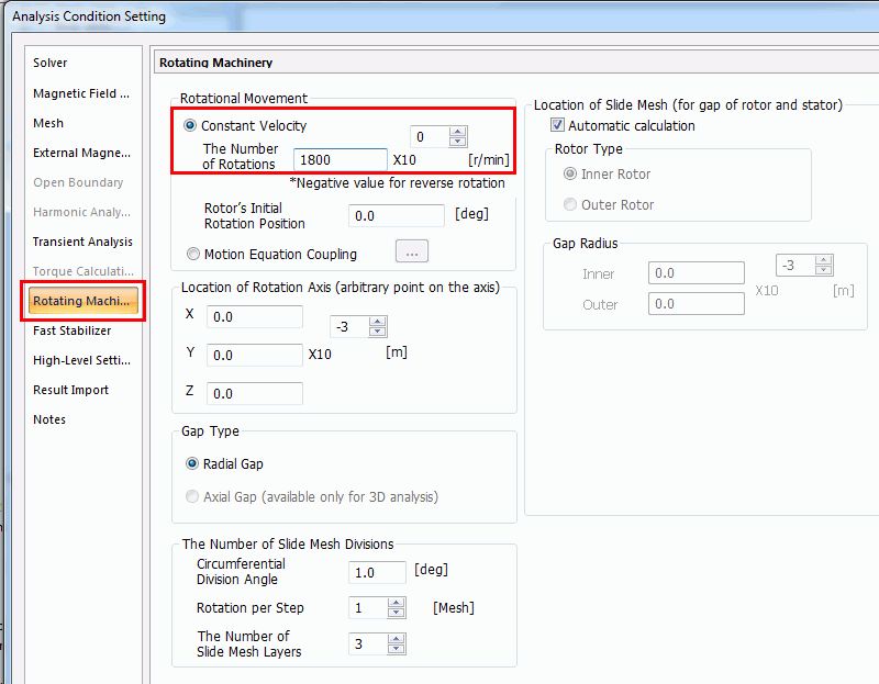
Click [Rotating Machinery] tab and set as follows;
Select [Rotational Movement]: [Constant Velocity]enter [Number of Rotations]: 1800 [r/min]
|
|
|
-
Click [Transient Analysis] tab and set as follows;
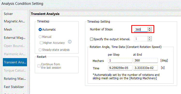
Enter [Number of Calculation Steps]:: 360.
-
The number of steps is 360, circumferential division angle is 1.0 [deg], and rotational quantity per step is 1 [mesh]. The mechanical angle rotation up to 360 [deg] (=360*1.0*1) is analyzed.
It can be converted to the electric angle of 720[ deg] (=360*4/2) ,(mechanical angle) x (number of poles). Two periods of electric angle are analyzed.
|
|
-
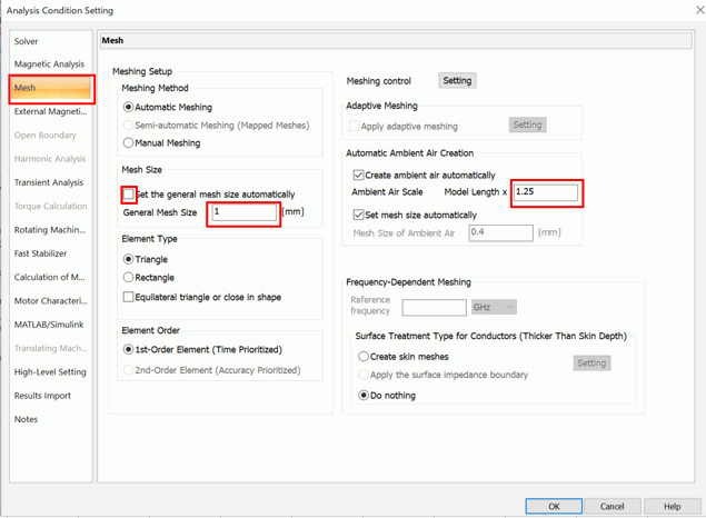
Click [Mesh] tab and set as follows;
Deselect [Set the general mesh size automatically]Enter 1 in [General mesh size]
Select [Create air domain automatically] and enter 1.25 in [Air Domain Scale].
Click  . .
-
The simulation accuracy varies depending on the mesh size and other settings.
Details are described at [How to Optimize the Simulation Accuracy].
|
|
|
The analysis conditions have been set. |
|


 Prev
Prev 