Home / Tutorial / Magnetic Analysis (Luvens, Transient Analysis of Motor) / 08.Define the External Circuit
08.Define the External Circuit
Define the external circuit as follows.
Procedure
-
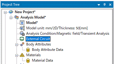
On the left side of the screen you will see [Project Tree]. Double click [External Circuit] .
[Circuit Editor] will show up.
|
|
-
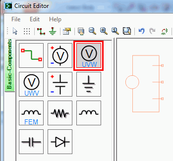
In the [Circuit Editor], click [3-Phase Voltage Source] on the component window.
Click anywhere in the circuit window on the right side and place the element.
|
|
-
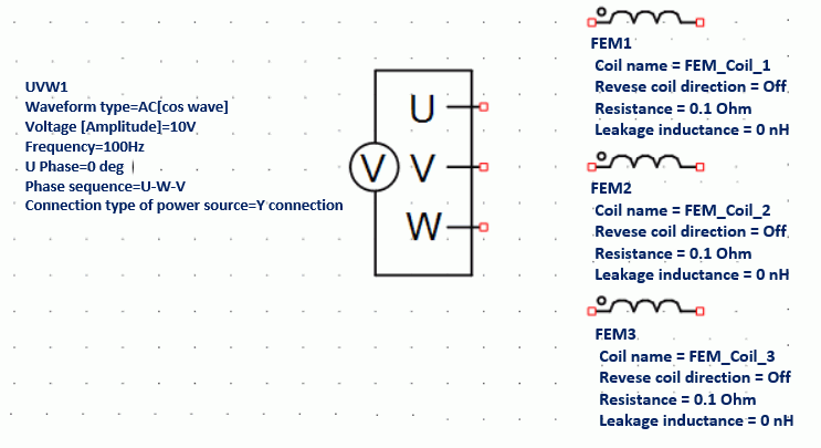
In the same way, place three elements below in the circuit window.
[FEM coils]: Place three coils from the top.
|
|
-
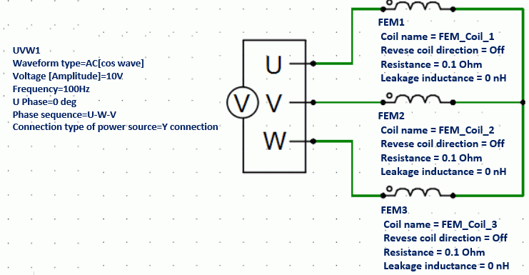
By clicking each port  one by one, connect elements as in the right figure. one by one, connect elements as in the right figure.
|
|
-
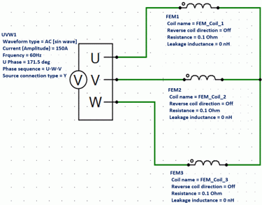
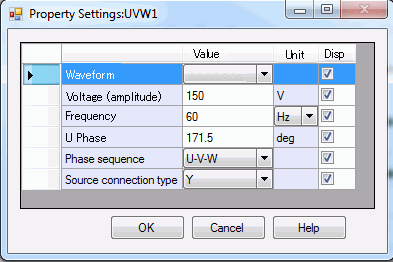
Double-click UVW 1 and set the parameters below, then click [OK].
[Waveform type]: AC (cos wave)
[Voltage (amplitude)]: 150[V]
[Frequency]: 60[Hz]
[Phase of U]: 171.5[deg]
[Phase sequence]: U-W-V[deg]
[Connection type of power source]: Y connection
|
|
-
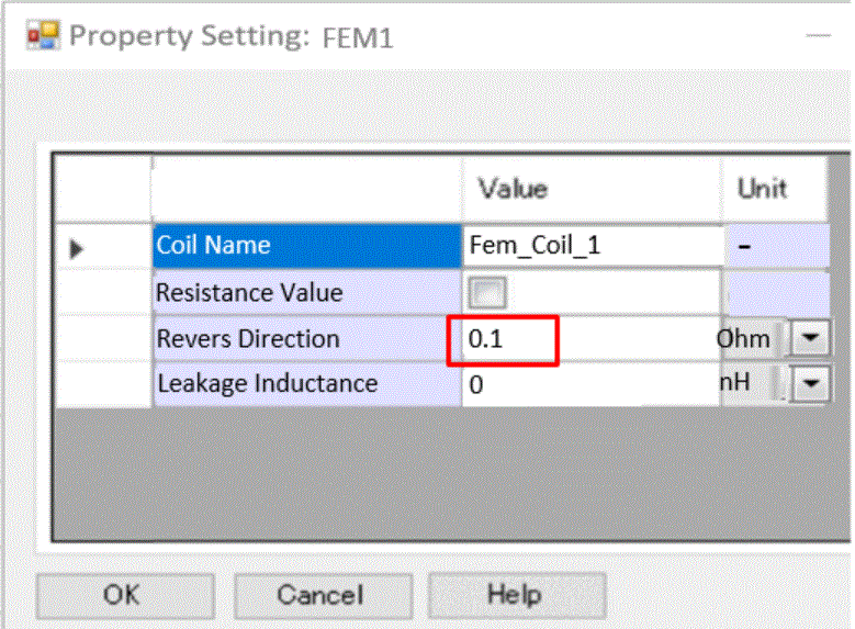
Likewise, set parameters below for three FEM coils and click [OK].
[Resistance]: 0.1[ohm]
-
Relate the name in the [Coil name] to the coil body of the model. (See the following page)
-
As [Conversion of external circuit I/O values] is ON, the resistance value of the FEM coil is set to the phase resistance which is equivalent to a full model instead of a quarter model.
-
See [External Circuit Conversion] and [Example of External Circuit Conversion Setup] for the details of conversion.
|
|
-
Lastly, check if the connection of elements and parameters match with the right figure.
Close the Circuit Editor. (X on the upper right of the window)
|
|
|
The definition of the external circuit is now completed. |
|


 Prev
Prev